Technical data
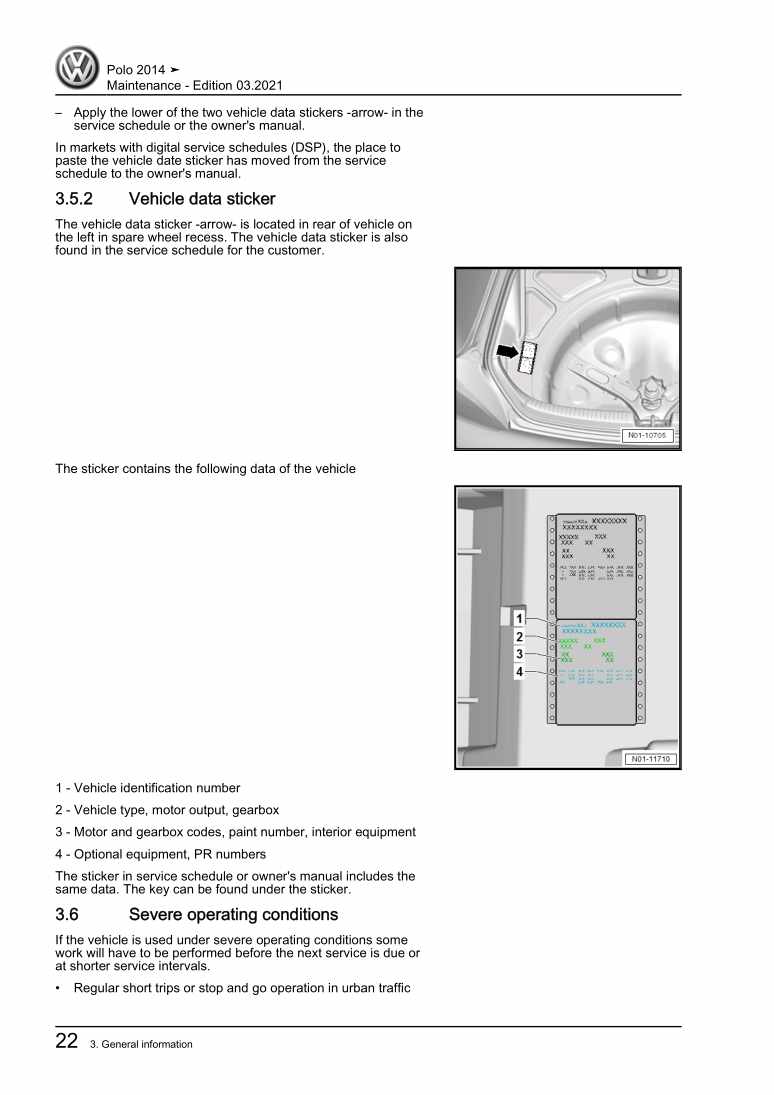
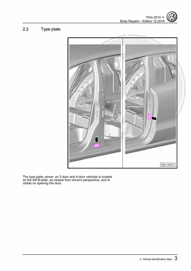
11 Identification
11.1 Engine number, engine data
12 Safety instructions
22.1 Safety precautions when working on fuel supply system
22.2 Safety precautions when working on vehicles with a Start/Stop system
22.4 Safety precautions when working on cooling system
32.5 Safety precautions when working on ignition system
33 Repair instructions
43.1 Rules for cleanliness
43.2 Foreign objects in engine
43.3 Contact corrosion
43.4 Routing and securing lines
43.5 Installing coolers, condensers and radiators
5Removing and installing engine
61 Removing and installing engine
61.1 Removing engine
61.2 Separating engine and gearbox
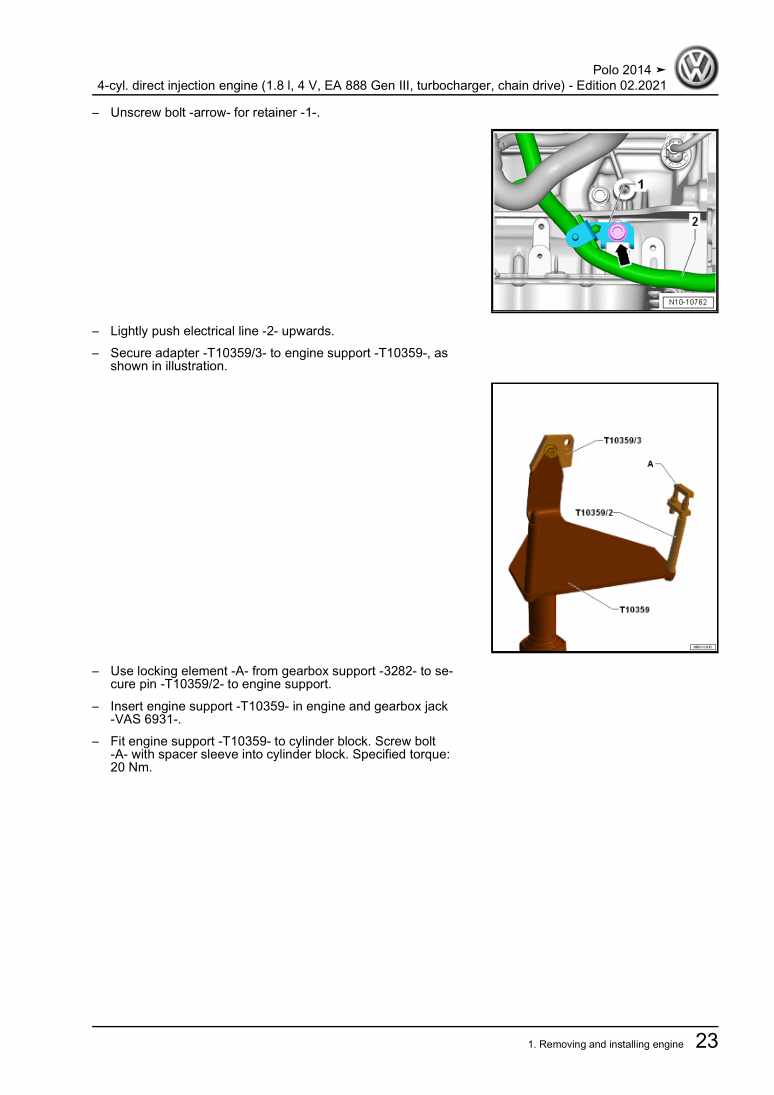
151.3 Securing engine on engine and gearbox support
171.4 Installing engine
182 Assembly mountings
212.1 Assembly overview - assembly mountings
212.2 Supporting engine in installation position
262.3 Removing and installing engine mountings
292.4 Removing and installing gearbox mounting
312.5 Removing and installing pendulum support
32Crankshaft group
351 Cylinder block (pulley end)
351.1 Assembly overview - poly V-belt drive
351.2 Assembly overview - Sealing flange, belt pulley end
381.3 Removing and installing poly V-belt
391.4 Removing and installing tensioner for poly V-belt
421.5 Removing and installing vibration damper
421.6 Removing and installing engine support
431.7 Renewing crankshaft oil seal - belt pulley end
471.8 Removing and installing sealing flange on pulley end
492 Cylinder block, gearbox end
522.1 Assembly overview - cylinder block, gearbox end
522.2 Removing and installing flywheel
532.3 Removing and installing sealing flange on gearbox side
543 Crankshaft
633.1 Renewing needle bearing in crankshaft
633.2 Crankshaft dimensions
643.3 Measuring axial clearance of crankshaft
644 Pistons and conrods
664.1 Assembly overview - pistons and conrods
664.2 Separating new conrod
684.3 Removing and installing pistons
684.4 Removing and installing oil spray jets
694.5 Checking piston and cylinder bore
704.6 Checking radial clearance of conrods
71Cylinder head, valve gear
721 Toothed belt drive
721.1 Assembly overview - toothed belt cover
721.2 Assembly overview - toothed belt
731.3 Checking valve timing
741.4 Detaching toothed belt from camshaft
801.5 Removing and installing toothed belt
942 Cylinder head
1092.1 Assembly overview - cylinder head
1092.2 Assembly overview - camshaft housing
1112.3 Removing and installing cylinder head
1122.4 Removing and installing camshaft housing
1162.5 Checking compression
1203 Valve gear
1233.1 Assembly overview - valve gear
1233.2 Removing and installing camshaft control valve 1 N205 / N318
1243.3 Removing and installing cam actuators
1253.4 Removing and installing camshaft adjuster
1283.5 Measuring axial play of camshaft
1293.6 Removing and installing camshaft oil seal
1303.7 Removing and installing valve stem seals
1354 Inlet and exhaust valves
1444.1 Checking valve guides
1444.2 Checking valves
1444.3 Valve dimensions
145Lubrication
1461 Sump, oil pump
1461.1 Assembly overview - sump, oil pump
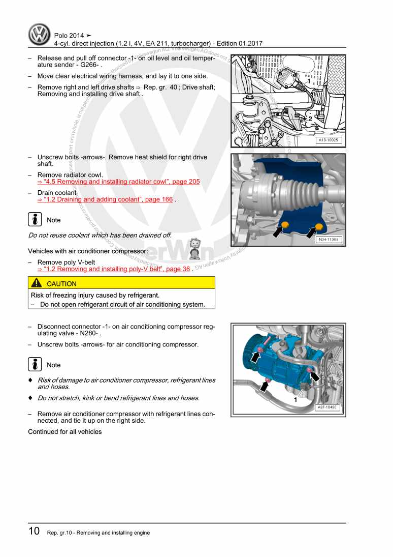
1461.2 Removing and installing oil level and oil temperature sender G266
1491.3 Removing and installing lower part of sump
1491.4 Removing and installing oil pump
1521.5 Removing and installing upper part of sump
1531.6 Engine oil
1562 Engine oil cooler
1572.1 Assembly overview - engine oil cooler
1572.2 Removing and installing engine oil cooler
1573 Crankcase breather
1593.1 Assembly overview - crankcase breather system
1593.2 Removing and installing oil separator
1604 Oil filter, oil pressure switch
1624.1 Assembly overview - oil filter/oil pressure switch
1624.2 Removing and installing oil pressure switch F1
1634.3 Removing and installing oil pressure switch for reduced oil pressure F378
1644.4 Removing and installing oil pressure regulating valve N428
1654.5 Checking oil pressure
166Cooling
1691 Cooling system, coolant
1691.1 Coolant hose schematic diagram
1691.2 Draining and filling coolant
1721.3 Checking cooling system for leaks
1782 Coolant pump, regulation of cooling system
1812.1 Assembly overview - coolant pump, thermostat
1812.2 Assembly overview - electric coolant pump
1832.3 Assembly overview - coolant temperature sender
1852.4 Removing and installing coolant pump
1862.5 Removing and installing toothed belt pulley for coolant pump
1902.6 Removing and installing thermostat
1942.7 Removing and installing electric coolant pump
1972.8 Removing and installing coolant temperature sender G62
1993 Coolant pipes
2023.1 Assembly overview - coolant pipes
2023.2 Removing and installing coolant pipes
2024 Radiator, radiator fan
2064.1 Assembly overview - radiator/radiator fan
2064.2 Assembly overview - radiator cowl and radiator fan
2084.3 Removing and installing radiator
2104.4 Removing and installing cooler for charge air cooling circuit
2134.5 Removing and installing radiator cowling with radiator fan
2174.6 Removing and installing radiator fan V7
218Turbocharging/supercharging
2201 Turbocharger
2201.1 Assembly overview - turbocharger
2201.2 Removing and installing turbocharger
2221.3 Removing and installing charge pressure positioner V465
2262 Charge air system
2302.1 Assembly overview - charge air system
2302.2 Removing and installing charge pressure sender GX26
2322.3 Removing and installing charge air cooler
2322.4 Checking charge air system for leaks
234Mixture preparation - injection
2361 Injection system
2361.1 Overview of fitting locations - injection system
2361.2 Releasing high pressure in fuel system
2392 Air filter
2412.1 Assembly overview - air filter housing
2412.2 Removing and installing air filter housing
2423 Intake manifold
2433.1 Assembly overview - intake manifold
2433.2 Removing and installing intake manifold
2453.3 Removing and installing throttle valve module GX3
2473.4 Cleaning throttle valve module GX3
2494 Injectors
2504.1 Assembly overview - fuel rail with injectors
2504.2 Removing and installing fuel rail
2514.3 Removing and installing injectors
2524.4 Cleaning injectors
2565 Senders and sensors
2585.1 Removing and installing intake manifold sender GX9
2585.2 Removing and installing fuel pressure sender G247
2585.3 Checking fuel pressure sender G247
2596 High-pressure pump
2636.1 Assembly overview - high-pressure pump
2636.2 Removing and installing high-pressure pump
2646.3 Removing and installing high-pressure pipe
2657 Lambda probe
2677.1 Assembly overview - Lambda probe
2677.2 Removing and installing Lambda probe
2688 Engine control unit
2708.1 Removing and installing engine control unit J623
2708.2 Removing and installing engine control unit J623 with protective housing
271Exhaust system
2731 Exhaust pipes, silencers
2731.1 Assembly overview - silencers
2731.2 Removing and installing silencer
2741.3 Separating exhaust pipes, silencers
2751.4 Aligning exhaust system free of stress
2761.5 Checking exhaust system for leaks
2772 Emission control
2782.1 Assembly overview - emission control
2782.2 Removing and installing catalytic converter
279Ignition system
2841 Ignition system
2841.1 Assembly overview - ignition system
2841.2 Test data, spark plugs
2851.3 Removing and installing ignition coils with output stage
2851.4 Removing and installing knock sensor 1 G61
2871.5 Removing and installing Hall sender
2881.6 Removing and installing engine speed sender G28
290
