Technical data
11 Marking
11.1 Engine number/engine data
12 General information
32.1 Numbering of cylinders
33 Safety information
43.1 Safety precautions when working on fuel system
43.2 Safety measures when working on vehicles with a start/stop system
53.4 Safety precautions when working on the cooling system
64 Repair instructions
74.1 Rules for cleanliness
74.2 Foreign objects in engine
84.3 Checking vacuum system
8Removing and installing engine
91 Removing and installing motor
91.1 Removing motor
91.2 Separating engine and gearbox
211.3 Securing engine on engine and gearbox support
261.4 Installing engine
282 Assembly mountings
322.1 Assembly overview - assembly mountings
322.2 Removing and installing engine mounting
342.3 Removing and installing gearbox mounting
422.4 Removing and installing pendulum support
432.5 Supporting engine in installation position
442.6 Adjusting assembly mountings
512.7 Checking adjustment of assembly mountings (engine and gearbox mountings)
533 Engine cover panel
553.1 Removing and installing engine cover
55Crankshaft group
561 Cylinder block (pulley end)
561.1 Assembly overview - poly V-belt drive
561.2 Assembly overview - sealing flange, belt pulley end
601.3 Removing and installing poly-V belt
621.4 Removing and installing tensioner for poly V-belt
661.5 Removing and installing vibration damper
681.6 Removing and installing bracket for ancillaries
691.7 Removing and installing engine bracket
711.8 Renewing crankshaft oil seal - belt pulley end
741.9 Removing and installing sealing flange on pulley end
772 Cylinder block, gearbox end
822.1 Assembly overview - cylinder block, gearbox end
822.2 Removing and installing flywheel
832.3 Removing and installing sealing flange on gearbox side
853 Crankshaft
993.1 Assembly overview - crankshaft
993.2 Crankshaft dimensions
1003.3 Renewing needle bearing in crankshaft
1003.4 Measuring axial clearance of crankshaft
1023.5 Measuring radial clearance of crankshaft
1034 Pistons and conrods
1054.1 Assembly overview - pistons and conrods
1054.2 Measuring piston projection at TDC
1074.3 Checking pistons and cylinder bores
1094.4 Separating new conrod
1124.5 Checking radial clearance of conrods
113Cylinder head, valve gear
1141 Cylinder head
1141.1 Assembly overview - cylinder head
1141.2 Assembly overview - cylinder head cover
1181.3 Removing and installing cylinder head
1201.4 Removing and installing cylinder head cover
1351.5 Removing and installing injector seals
1381.6 Removing and installing vacuum pump
1391.7 Checking compression
1412 Toothed belt drive
1442.1 Assembly overview - toothed belt
1442.2 Removing and installing toothed belt
1473 Valve gear
1713.1 Assembly overview - valve gear
1713.2 Measuring axial play of camshaft
1733.3 Measuring radial play of camshaft
1743.4 Removing and installing camshaft oil seal
1753.5 Removing and installing camshaft
1833.6 Checking hydraulic compensation elements
1923.7 Removing and installing valve stem seals
1934 Inlet and exhaust valves
2024.1 Reworking valve seats
2024.2 Checking valve guides
2024.3 Checking valves
2034.4 Valve dimensions
203Lubrication
2041 Sump, oil pump
2041.1 Assembly overview - sump/oil pump
2041.2 Engine oil:
2101.3 Removing and installing oil sump
2111.4 Removing and installing oil pump
2151.5 Removing and installing oil level and oil temperature sender G266
2182 Engine oil cooler
2202.1 Assembly overview - engine oil cooler
2202.2 Removing and installing engine oil cooler
2203 Oil filter, oil pressure switch
2243.1 Assembly overview - oil filter housing, oil pressure switch
2243.2 Removing and installing oil pressure switch F1
2253.3 Checking oil pressure
2263.4 Checking oil pressure and oil pressure switch
2273.5 Removing and installing oil filter housing
2284 Oil circuit
2334.1 Assembly overview - oil circuit
2334.2 Removing and installing oil return line for turbocharger
2335 Balancer shaft module
2395.1 Removing and installing balance shaft module
239Cooling
2491 Cooling system/coolant
2491.1 Connection diagram - coolant hoses
2491.2 Checking cooling system for leaks
2511.3 Draining and adding coolant
2522 Coolant pump, regulation of cooling system
2612.1 Assembly overview - coolant pump, thermostat
2612.2 Assembly overview - electric coolant pump
2612.3 Removing and installing electric coolant pump
2622.4 Removing and installing coolant pump
2652.5 Removing and installing 4/2-way valve with thermostat
2672.6 Removing and installing coolant temperature sender G62
2732.7 Removing and installing radiator outlet coolant temperature sender G83
2753 Coolant pipes
2783.1 Assembly overview - coolant pipes
2783.2 Removing and installing coolant pipes
2804 Radiator, radiator fan
2934.1 Assembly overview - radiator/radiator fan
2934.2 Removing and installing radiator
2944.3 Removing and installing radiator cowl with radiator fan
2954.4 Removing and installing radiator fan
297Turbocharging/supercharging
2981 Turbocharger
2981.1 Assembly overview - turbocharger
2981.2 Removing and installing turbocharger
3001.3 Renewing vacuum unit for turbocharger
3072 Charge air system
3152.1 Assembly overview - charge air system
3152.2 Assembly overview - charge-air hose connections
3172.3 Removing and installing charge air cooler
3192.4 Removing and installing charge pressure sender G31
3212.5 Checking charge air system for leaks
322Mixture preparation - injection
3261 Injection system
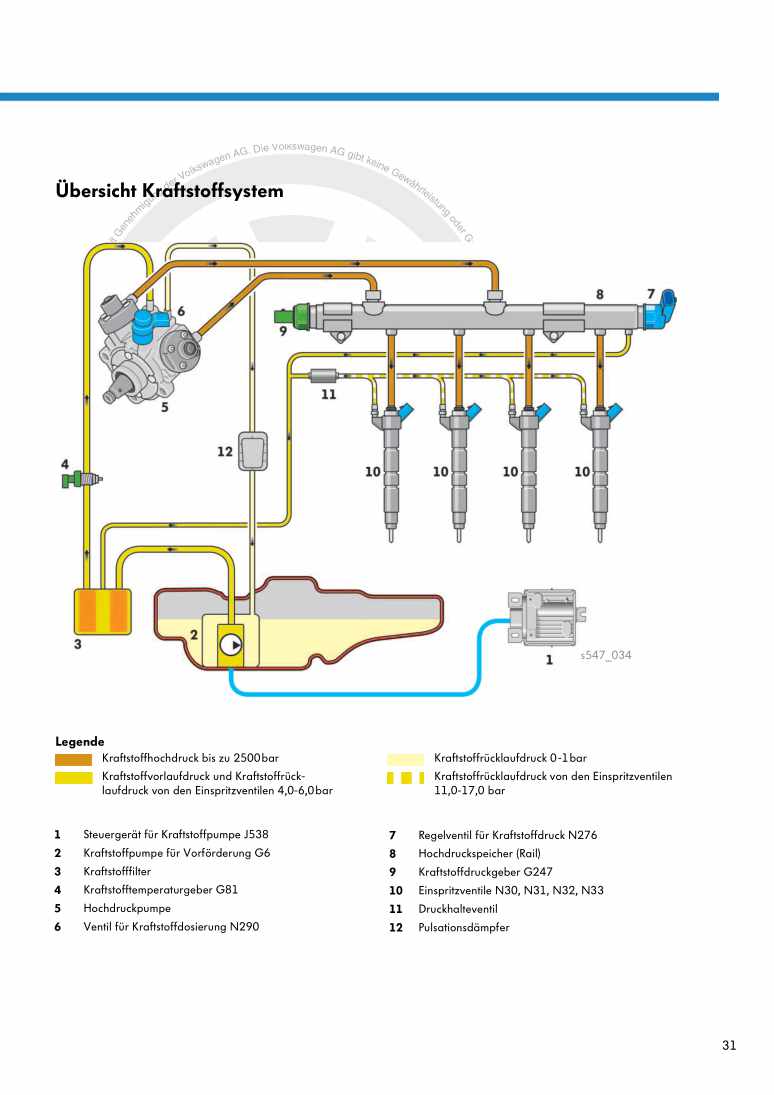
3261.1 Schematic overview - fuel system
3261.2 Filling/bleeding fuel system
3281.3 Checking fuel system for leaks
3292 Vacuum system
3302.1 Assembly overview - vacuum system
3302.2 Checking vacuum system
3313 Injectors/high-pressure accumulator (rail)
3353.1 Assembly overview - injectors
3353.2 Assembly overview - fuel system
3363.3 Adapting correction values for injectors
3393.4 Testing jammed-open injectors
3403.5 Removing and installing injectors
3413.6 Removing and installing high-pressure lines
3453.7 Removing and installing fuel rail
3494 Air filter
3544.1 Assembly overview - air filter housing
3544.2 Removing and installing air filter housing
3565 Intake manifold
3595.1 Assembly overview - intake manifold
3595.2 Removing and installing intake manifold
3615.3 Removing and installing throttle valve module J338
3656 Senders and sensors
3676.1 Checking fuel pressure regulating valve N276
3676.2 Removing and installing fuel pressure regulating valve N276
3686.3 Removing and installing fuel pressure sender G247
3706.4 Removing and installing air mass meter G70
3736.5 Removing and installing pressure differential sender G505
3747 Engine (motor) control unit
3787.1 Removing and installing engine control unit J623
3787.2 Removing and installing engine (motor) control unit J623 with protective housing
3798 High-pressure pump
3828.1 Assembly overview - high-pressure pump
3828.2 Removing and installing high-pressure pump
3849 Lambda probe
3919.1 Removing and installing Lambda probe
391Exhaust system
3931 Exhaust pipes and silencers
3931.1 Assembly overview - silencers
3931.2 Removing and installing rear silencer
3951.3 Aligning exhaust system free of stress
3971.4 Installation position of clamp
3982 Emission control
4002.1 Assembly overview - emission control
4002.2 Removing and installing particulate filter
4033 Exhaust gas temperature regulation
4123.1 Removing and installing parts of exhaust gas temperature regulation
4124 Exhaust gas recirculation
4194.1 Assembly overview - exhaust gas recirculation
4194.2 Removing and installing exhaust gas recirculation cooler
4214.3 Checking changeover for exhaust gas recirculation cooler
4244.4 Checking exhaust gas recirculation cooler for leaks
4254.5 Cleaning exhaust gas recirculation system
430Glow plug system
4381 Glow plug system
4381.1 Removing and installing glow plug
4381.2 Removing and installing automatic glow period control unit J179
4401.3 Removing and installing Hall sender G40
4421.4 Removing and installing engine speed sender G28
443
