Technical data
11 Safety information
11.1 Safety regulations for working on fuel supply
11.2 Safety precautions when working on charge air system
21.3 Safety precautions when working on injection system
21.4 Safety precautions when working on the cooling system
32 Identification
52.1 Engine number/engine data
53 Repair instructions
73.1 General notes on the lubrication system
73.2 General notes on fuel system
73.3 Instructions for working on fuel system
83.4 Rules for cleanliness when working on fuel supply system
103.5 Rules for cleanliness during work on fuel system
103.6 Rules for cleanliness when working on injection system
11Removing and installing engine
121 Removing and installing engine
121.1 Removing engine
121.2 Securing engine on engine and gearbox support
301.3 Installing engine
321.4 Modifying engine bracket T10229
351.5 Converting adapter 10 - 222 A /23 with adapter 10 - 222 A /23-1
362 Assembly mountings
382.1 Assembly overview - assembly mountings
382.2 Supporting engine in installation position
402.3 Removing and installing engine mounting
412.4 Removing and installing engine mounting
47Crankshaft group
511 Cylinder block (pulley end)
511.1 Assembly overview - cylinder block (pulley end)
511.2 Assembly overview - sealing flange, belt pulley end
531.3 Assembly overview - poly V-belt drive
551.4 Removing and installing poly-V belt
611.5 Removing and installing tensioner for poly V-belt
631.6 Removing and installing bracket for ancillaries
641.7 Removing and installing vibration damper
671.8 Renewing crankshaft oil seal - belt pulley end
681.9 Removing and installing sealing flange on pulley end
712 Cylinder block, gearbox end
772.1 Assembly overview - cylinder block, gearbox end
772.2 Removing and installing flywheel
782.3 Removing and installing sealing flange on gearbox side
803 Crankshaft
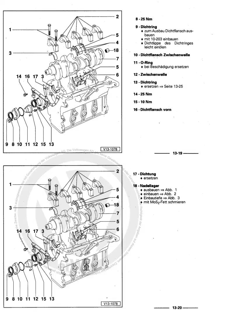
923.1 Assembly overview - crankshaft
923.2 Crankshaft dimensions
933.3 Allocation of main bearing shells
943.4 Measuring axial clearance of crankshaft
943.5 Measuring radial clearance of crankshaft
953.6 Renewing needle bearing in crankshaft
963.7 Renewing spur gear for crankshaft
984 Pistons and conrods
1024.1 Assembly overview - pistons and conrods
1024.2 Removing and installing pistons
1054.3 Separating new conrod
1064.4 Checking pistons and cylinder bores
1074.5 Checking radial clearance of conrods
1084.6 Measuring piston projection at TDC
1094.7 Removing and installing oil spray jets
111Cylinder head, valve gear
1131 Cylinder head
1131.1 Assembly overview - cylinder head
1131.2 Assembly overview - cylinder head cover
1171.3 Removing and installing cylinder head
1221.4 Removing and installing cylinder head cover
1341.5 Removing and installing injector seals
1411.6 Removing and installing vacuum pump
1451.7 Checking compression
1492 Fully enclosing toothed belt guard
1512.1 Assembly overview - fully enclosing toothed belt guard
1512.2 Removing and installing upper toothed belt guard (fully enclosing)
1532.3 Removing and installing lower toothed belt guard (fully enclosed)
1542.4 Removing and installing rear toothed belt guard (fully enclosing)
1563 Toothed belt drive
1603.1 Assembly overview - toothed belt
1603.2 Removing and installing toothed belt
1624 Valve gear
1804.1 Assembly overview - valve gear
1804.2 Measuring axial play of camshaft
1834.3 Measuring radial play of camshaft
1844.4 Removing and installing camshaft oil seal
1844.5 Removing and installing camshaft
1874.6 Checking hydraulic compensation elements
1964.7 Removing and installing valve stem seals
1975 Inlet and exhaust valves
2025.1 Reworking valve seats
2025.2 Checking valve guides
2025.3 Valve dimensions
203Lubrication
2041 Sump, oil pump
2041.1 Assembly overview - sump/oil pump
2041.2 Removing and installing sump
2101.3 Removing and installing oil pump
2151.4 Engine oil:
2171.5 Removing and installing oil level and oil temperature sender G266
2182 Engine oil cooler
2202.1 Assembly overview - engine oil cooler
2202.2 Removing and installing engine oil cooler
2222.3 Checking engine oil cooler for leaks
2263 Oil filter, oil pressure switch
2293.1 Assembly overview - oil filter housing
2293.2 Removing and installing oil pressure switch F1
2293.3 Checking oil pressure
2303.4 Removing and installing oil filter housing, mono-turbo
2323.5 Measuring oil consumption
2354 Balancer shaft module
2374.1 Removing and installing balance shaft module
237Cooling
2451 Cooling system/coolant
2451.1 Draining and adding coolant
2451.2 Checking cooling system for leaks
2541.3 Assembly overview - coolant hoses
2561.4 Connection diagram for coolant hoses - vehicles with basic equipment
2581.5 Connection diagram for coolant hoses - vehicles with additional heat exchanger
2601.6 Connection diagram for coolant hoses - vehicles with auxiliary heater
2652 Coolant pump, regulation of cooling system
2872.1 Assembly overview - coolant pump and ball thermostat (4/2-way valve)
2872.2 Assembly overview - Continued coolant circulation pump V51
2882.3 Removing and installing coolant pump
2882.4 Removing and installing continued coolant circulation pump V51
2912.5 Removing and installing 4/2-way valve with thermostat
2932.6 Removing and installing Y-thermostat
2982.7 Removing and installing coolant temperature sender G62
2992.8 Removing and installing radiator outlet coolant temperature sender G83
3023 Radiator, radiator fan
3073.1 Assembly overview - radiator/radiator fan
3073.2 Assembly overview – radiator cowl and radiator fan
3093.3 Removing and installing radiator
3093.4 Removing and installing radiator cowl with radiator fan V7
317Fuel supply system
3191 Procedure in event of misfuelling
3191.1 Procedure in event of misfuelling
3192 Fuel
3232.1 Assembly overview - fuel tank
3232.2 Removing and installing fuel tank
3253 Fuel delivery unit, fuel gauge sender
3303.1 Removing and installing fuel delivery unit
3303.2 Removing and installing fuel gauge sender G
3314 Fuel pump
3324.1 Assembly overview - supplementary fuel pump V393
3324.2 Removing and installing supplementary fuel pump V393
3344.3 Checking supplementary fuel pump V393
3374.4 Checking delivery pressure of fuel system pressurisation pump G6
3394.5 Checking fuel delivery rate of fuel system pressurisation pump G6
3404.6 Checking voltage supply of fuel system pressurisation pump G6
3424.7 Checking current draw of fuel system pressurisation pump G6
3435 Accelerator pedal
3465.1 Function
3465.2 Assembly overview - accelerator mechanism
346Turbocharging/supercharging
3481 Turbocharger
3481.1 Assembly overview - turbocharger
3481.2 Assembly overview – connecting pipes (bi-turbo)
3581.3 Removing and installing turbocharger
3601.4 Removing and installing exhaust manifold gasket (bi-turbo)
3951.5 Removing and installing compressor housing and turbine housing (bi-turbo)
4051.6 Checking vacuum unit for turbocharger
4081.7 Renewing vacuum unit for turbocharger
4171.8 Removing and installing connecting pipes (bi-turbo)
4312 Charge air system
4392.1 Assembly overview - charge air system
4392.2 Assembly overview - charge-air hose connections
4432.3 Removing and installing charge air cooler
4472.5 Removing and installing exhaust gas flap valve N220
4532.7 Removing and installing charge pressure control solenoid valve N75
4542.8 Checking charge air system for leaks
4562.9 Removing and installing charge pressure sender 2 G447
460Mixture preparation - injection
4621 Injection system
4621.1 Overview of fitting locations - injection system
4621.2 Schematic overview - fuel system
4721.3 Assembly overview - fuel system
4741.4 Checking fuel system for leaks
4802 Vacuum system
4812.1 Connection diagram - vacuum system
4812.2 Testing vacuum system for leaks, bi-turbo
4852.3 Testing vacuum system for leaks, mono-turbo
4942.4 Checking vacuum system for leaks, “four-wheel drive”
5013 Injectors/high-pressure accumulator (rail)
5093.1 Removing and installing fuel rail
5093.2 Removing and installing high-pressure lines
5133.3 Removing and installing injectors
5203.4 Testing injectors
5263.5 Testing jammed-open injectors
5343.6 Check pressure retention valve in fuel return line
5363.7 Checking low pressure fuel system
5393.8 Checking fuel pump delivery rate
5414 Air filter
5434.1 Assembly overview - air filter housing
5434.2 Removing and installing air filter housing
5465 Intake manifold
5495.1 Assembly overview – intake manifold
5495.2 Removing and installing intake manifold
5495.3 Removing and installing throttle valve module GX3
5546 Senders and sensors
5566.1 Removing and installing air mass meter G70
5566.2 Removing and installing fuel pressure regulating valve N276
5576.3 Checking fuel pressure regulating valve N276
5606.4 Removing and installing fuel pressure sender G247
5626.5 Removing and installing exhaust gas pressure sensor 1 G450
5647 Engine control unit
5687.1 Removing and installing engine control unit J623
5688 High-pressure pump
5708.1 Removing and installing high-pressure pump
5708.2 Checking high-pressure pump
574Exhaust system
5781 Exhaust pipes and silencers
5781.1 Assembly overview – silencers
5781.2 Removing and installing front exhaust pipe
5821.3 Separating exhaust pipes from silencers
5841.4 Checking exhaust system for leaks
5851.5 Aligning exhaust system free of stress
5861.6 Installation position of clamp
5872 Emission control
5882.1 Assembly overview - particulate filter
5882.2 Assembly overview - catalytic converter, four-wheel drive vehicles
5932.3 Removing and installing particulate filter
5952.4 Removing and installing catalytic converter, four-wheel drive vehicles
6023 Exhaust gas recirculation
6053.1 Assembly overview – exhaust gas recirculation
6053.2 Removing and installing exhaust gas recirculation cooler
6083.3 Removing and installing exhaust gas recirculation valve 1 GX5
6203.4 Pressure loss test for exhaust gas recirculation cooler
621Glow plug system
6251 Glow plug system
6251.1 Checking glow plug system
6251.2 Removing and installing glow plug
6251.3 Checking glow plug
6281.4 Optical characteristics of glow plugs
6291.5 Removing and installing engine speed sender G28
6291.6 Removing and installing Hall sender G40
631