Technical data
11 Identification
11.1 Engine number/engine data
12 Safety information
22.1 Safety precautions when working on fuel system
22.2 Safety measures when working on vehicles with a start/stop system
22.4 Safety precautions when working on the cooling system
32.5 Safety precautions when working on exhaust system
32.6 Safety precautions when working on the SCR system
43 Repair notes
63.1 Identification labels
63.2 Using impact drivers
63.3 Rules for cleanliness
73.4 General notes
73.5 General repair notes
93.6 Foreign objects in engine
103.7 Contact corrosion
113.8 Routing and attachment of lines
113.9 Fitting radiator and condensers
113.10 Adapting after component replacement
12Removing and installing engine
131 Removing and installing engine
131.1 Removing engine
131.2 Separating engine and gearbox
361.3 Securing engine on engine and gearbox support
421.4 Installing engine
462 Assembly mountings
502.1 Assembly overview - assembly mountings
502.2 Removing and installing engine mounting
542.3 Removing and installing gearbox mounting
592.4 Supporting engine in installation position
602.5 Removing and installing power unit mounting senders
642.6 Removing and installing power unit mounting control unit J931
642.7 Calibrating electrohydraulic engine mounting
653 Engine cover panel
673.1 Removing and installing engine cover
67Crankshaft group
691 Cylinder block (pulley end)
691.1 Assembly overview - cylinder block (pulley end)
691.2 Assembly overview - sealing flange, belt pulley end
761.3 Removing and installing poly-V belt
791.4 Removing and installing tensioner for poly V-belt
831.5 Removing and installing vibration damper
861.6 Removing and installing bracket for ancillaries
931.7 Removing and installing engine support
971.8 Renewing crankshaft oil seal - belt pulley end
981.9 Removing and installing sealing flange on pulley end
992 Cylinder block, gearbox end
1052.1 Assembly overview - cylinder block, gearbox end
1052.2 Removing and installing drive plate
1052.3 Renewing crankshaft oil seal (gearbox end)
1083 Crankshaft
1113.1 Assembly overview - crankshaft
1113.2 Crankshaft dimensions
1143.3 Allocation of main bearing shells
1143.4 Measuring axial clearance of crankshaft
1153.5 Measuring radial clearance of crankshaft
1163.6 Checking sender wheel
1174 Balancer shaft
1194.1 Assembly overview - balance shaft
1194.2 Removing and installing balance shaft
1204.3 Renewing roller bearing
1285 Pistons and conrods
1315.1 Assembly overview - pistons and conrods
1315.2 Removing and installing pistons
1355.3 Measuring piston projection at TDC
1365.4 Checking pistons and cylinder bores
1385.5 Checking radial clearance of conrods
140Cylinder head, valve gear
1421 Cover for timing chain
1421.1 Assembly overview - cover for timing chain
1421.2 Removing and installing timing chain cover
1472 Chain drive
1582.1 Assembly overview - camshaft timing chains
1582.2 Assembly overview - drive chain
1602.3 Removing camshaft timing chain from camshafts
1622.4 Removing and installing camshaft timing chain
1742.5 Removing and installing drive chain for high-pressure pump
1852.6 Installing intermediate drive
1873 Cylinder head
1963.1 Assembly overview - cylinder head
1963.2 Assembly overview - cylinder head cover
1993.3 Removing and installing cylinder head
2023.4 Removing and installing cylinder head cover
2113.5 Removing and installing injector seals
2163.6 Checking compression
2174 Valve gear
2194.1 Assembly overview - valve gear
2194.2 Measuring axial play of camshaft
2284.3 Measuring radial play of camshaft
2304.4 Removing and installing camshaft
2314.5 Removing and installing valve stem seals
2475 Inlet and exhaust valves
2575.1 Reworking valve seats
2575.2 Checking valve guides
2575.3 Checking valves
2585.4 Valve dimensions
258Lubrication
2591 Sump, oil pump
2591.1 Assembly overview - sump/oil pump
2591.2 Engine oil:
2631.3 Removing and installing lower part of sump
2631.4 Removing and installing upper part of sump
2671.5 Removing and installing oil pump
2701.6 Removing and installing oil level and oil temperature sender G266
2722 Engine oil cooler
2742.1 Assembly overview - engine oil cooler
2742.2 Removing and installing engine oil cooler
2762.3 Removing and installing temperature regulator for engine oil cooler
2773 Oil filter, oil pressure switch
2793.1 Assembly overview - oil filter
2793.2 Removing and installing oil filter housing
2813.3 Removing and installing oil pressure sender G10
2833.4 Checking oil pressure
2843.5 Removing and installing oil pressure regulating valve N428
2853.6 Removing and installing oil temperature sender 2 G664
285Cooling
2881 Cooling system/coolant
2881.1 Connection diagram - coolant hoses
2881.2 Assembly overview – coolant expansion tank
2921.3 Checking cooling system for leaks
2931.4 Draining and adding coolant
2972 Coolant pump, regulation of cooling system
3062.1 Assembly overview - coolant pump
3062.2 Assembly overview - electric coolant pump
3072.3 Assembly overview - thermostat
3092.4 Assembly overview – coolant valves
3112.5 Assembly overview - coolant temperature sender
3142.6 Removing and installing electric coolant pump
3162.7 Removing and installing coolant pump
3192.8 Removing and installing map-controlled engine cooling thermostat F265
3222.10 Removing and installing coolant temperature sender G62
3232.12 Removing and installing coolant temperature sender 2 G802
3262.13 Removing and installing coolant temperature sender for charge air cooler G1130
3272.14 Removing and installing coolant valves
3293 Coolant pipes
3353.1 Assembly overview - coolant pipes
3353.2 Removing and installing coolant pipes
3403.3 Removing and installing coolant line
3604 Radiator, radiator fan
3624.1 Assembly overview - radiator/radiator fan
3624.2 Assembly overview – radiator cowl and radiator fan
3654.3 Assembly overview - radiator blind
3664.4 Assembly overview - auxiliary radiator
3674.5 Removing and installing radiator
3684.6 Removing and installing radiator blind
3724.7 Removing and installing radiator blind control motor V544
3734.8 Removing and installing water radiator for charge air cooling circuit
3754.9 Removing and installing radiator cowl
3774.10 Removing and installing radiator fan
3804.11 Removing and installing auxiliary radiator
381Turbocharging/supercharging
3841 Turbocharger
3841.1 Assembly overview - turbocharger
3841.2 Removing and installing turbocharger
3882 Charge air system
3922.1 Assembly overview - charge air system
3922.2 Assembly overview - charge-air hose connections
3942.3 Removing and installing charge air cooler
3952.4 Removing and installing charge pressure sender G31
3982.5 Removing and installing charge air temperature sender
3992.6 Checking charge air system for leaks
400Mixture preparation - injection
4051 Injection system
4051.1 Schematic overview - fuel system
4051.2 Overview of fitting locations - injection system
4061.3 Filling/bleeding fuel system
4131.4 Checking fuel system for leaks
4142 Vacuum system
4152.1 Connection diagram – vacuum system
4152.2 Checking vacuum system
4153 Air filter
4173.1 Assembly overview - air filter housing
4173.2 Removing and installing air filter housing
4194 Intake manifold
4234.1 Assembly overview – intake manifold
4234.2 Removing and installing intake manifold upper part
4264.3 Removing and installing lower part of intake manifold
4304.4 Removing and installing intake manifold flap control unit GX14
4314.5 Removing and installing throttle valve module GX3
4325 Injectors/high-pressure accumulator (rail)
4345.1 Assembly overview - injectors
4345.2 Testing injectors
4395.3 Adapting correction values for injectors
4395.4 Checking return flow rate of injectors with engine running
4405.5 Checking return flow rate of injectors at starter speed
4455.6 Removing and installing injectors
4505.7 Removing and installing high-pressure lines
4625.8 Removing and installing fuel rail
4646 Senders and sensors
4706.1 Removing and installing air mass meter G70
4706.2 Removing and installing fuel temperature sender G81
4716.3 Removing and installing fuel pressure sender G247
4726.4 Removing and installing fuel pressure sender for low-pressure G410
4746.5 Checking fuel pressure regulating valve N276
4756.6 Removing and installing fuel pressure regulating valve N276
4776.7 Removing and installing pressure differential sender
4806.8 Removing and installing NOx sender
4826.9 Removing and installing particle sensor G784
4867 High-pressure pump
4897.1 Assembly overview - high-pressure pump
4897.2 Removing and installing high-pressure pump
4918 Lambda probe
4968.1 Assembly overview - Lambda probe
4968.2 Removing and installing Lambda probe
4999 Engine control unit
5039.1 Assembly overview – engine/motor control unit
5039.2 Removing and installing engine control unit J623
503Exhaust system
5051 Exhaust pipes and silencers
5051.1 Assembly overview – silencers
5051.2 Removing and installing front exhaust pipe
5071.3 Separating exhaust pipes from silencers
5101.4 Removing and installing silencer
5121.5 Aligning exhaust system free of stress
5141.6 Checking exhaust system for leaks
5151.7 Installation position of clamp
5162 Emission control
5182.1 Assembly overview – emission control
5182.2 Removing and installing emission control module
5212.3 Removing and installing trap catalytic converter
5252.4 Removing and installing exhaust flap control unit J883
5273 SCR system (selective catalytic reduction)
5293.1 Assembly overview – reducing agent tank
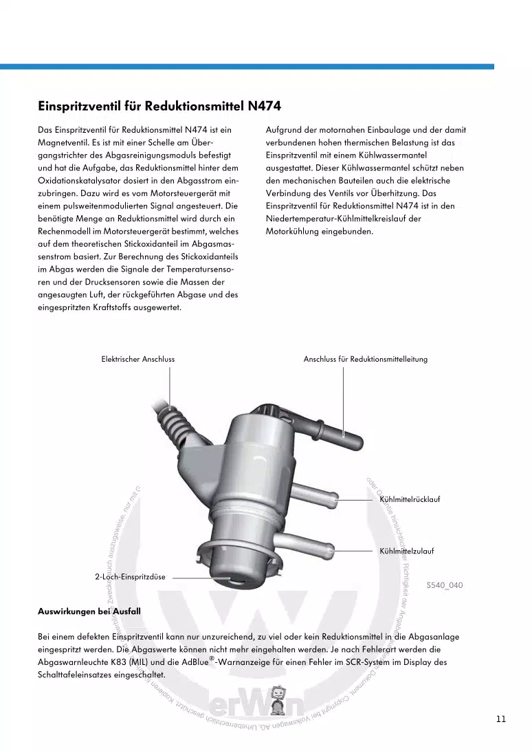
5293.2 Assembly overview - injector for reducing agent
5323.3 Assembly overview - reducing agent supply line
5353.4 Relieving pressure in SCR system
5363.5 Disconnecting reducing agent supply line
5373.6 Draining reducing agent tank
5393.7 Removing and installing reducing agent tank
5413.8 Removing and installing injector for reduction agent N474
5433.9 Removing and installing injector 2 for reducing agent N758
5453.10 Removing and installing control unit for reducing agent metering system J880
5473.11 Removing and installing reducing agent quality sensor G849
5483.12 Removing and installing pump for reducing agent V437
5483.14 Removing and installing connection for SCR supply line
5534 Exhaust gas temperature regulation
5564.1 Assembly overview – exhaust gas temperature regulation
5564.2 Removing and installing exhaust gas temperature sender 1 G235
5574.3 Removing and installing exhaust gas temperature sender 2 G448
5594.4 Removing and installing exhaust gas temperature sender 3 G495
5604.5 Removing and installing exhaust gas temperature sender 4 G648
5615 Exhaust gas recirculation
5645.1 Assembly overview – exhaust gas recirculation
5645.2 Removing and installing exhaust gas recirculation cooler
5685.3 Removing and installing exhaust gas recirculation valve 2 GX6
5735.4 Removing and installing exhaust gas recirculation temperature sensor G98
5746 Exhaust manifold
5766.1 Assembly overview - exhaust manifold
5766.2 Removing and installing exhaust manifold
577Ignition system
5811 Glow plug system
5811.1 Assembly overview - glow plug system
5811.2 Removing and installing glow plug
5831.3 Removing and installing automatic glow period control unit J179
5871.4 Removing and installing Hall sender G40
5881.5 Removing and installing engine speed sender G28
589