Technical data
11 Safety information
11.1 Safety regulations for working on fuel supply
11.2 Safety measures when working on vehicles with a start/stop system
11.4 Safety precautions when working on the cooling system
21.5 Safety precautions when working on ignition system
22 Identification
32.1 Engine number/engine data
33 Repair instructions
53.1 Rules for cleanliness
53.2 Foreign objects in engine
53.3 Contact corrosion
53.4 Routing and attachment of lines
63.5 Fitting radiator and condensers
63.6 Checking vacuum system
6Removing and installing engine
71 Removing and installing engine
71.1 Removing engine
71.2 Separating engine and gearbox
181.3 Securing engine on engine and gearbox support
201.4 Installing engine
222 Assembly mountings
252.1 Assembly overview - assembly mountings
252.2 Removing and installing engine mounting
282.3 Removing and installing gearbox mounting
302.4 Removing and installing pendulum support
312.5 Supporting engine in installation position
322.6 Adjusting assembly mountings
402.7 Checking adjustment of assembly mountings
423 Engine cover panel
433.1 Removing and installing engine cover
43Crankshaft group
441 Cylinder block (pulley end)
441.1 Assembly overview - cylinder block (pulley end)
441.2 Removing and installing poly-V belt
471.3 Removing and installing tensioner for poly V-belt
481.4 Removing and installing vibration damper
491.5 Removing and installing bracket for ancillaries
561.6 Removing and installing engine support
602 Cylinder block, gearbox end
622.1 Assembly overview - cylinder block, gearbox end
622.2 Assembly overview - drive plate
632.3 Removing and installing drive plate
642.4 Removing and installing flywheel
662.5 Removing and installing sealing flange on gearbox side
683 Crankshaft
733.1 Assembly overview - crankshaft
733.2 Crankshaft dimensions
763.3 Allocation of main bearing shells
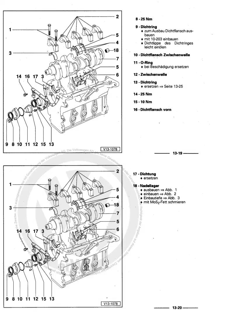
763.4 Renewing needle bearing in crankshaft
783.5 Measuring axial clearance of crankshaft
813.6 Measuring radial clearance of crankshaft
823.7 Removing and installing sender wheel
834 Balancer shaft
854.1 Assembly overview - balance shaft
854.2 Removing and installing balance shaft
874.3 Renewing oil seal for balance shaft (inlet side)
925 Pistons and conrods
945.1 Assembly overview - pistons and conrods
945.2 Removing and installing pistons
985.3 Checking pistons and cylinder bores
1005.4 Separating new conrod
1015.5 Checking radial clearance of conrods
1025.6 Removing and installing oil spray jets
102Cylinder head, valve gear
1051 Cylinder head
1051.1 Assembly overview - cylinder head
1051.2 Removing and installing cylinder head
1081.3 Assembly overview - vacuum pump
1141.4 Removing and installing vacuum pump
1151.5 Checking compression
1172 Cover for timing chain
1202.1 Assembly overview - cover for timing chain
1202.3 Removing and installing timing chain cover
1222.4 Renewing seal for vibration damper
1303 Chain drive
1343.1 Assembly overview - camshaft timing chains
1343.2 Assembly overview - drive chain for balance shaft
1373.3 Removing and installing camshaft timing chain
1403.4 Removing and installing drive chain for balance shaft
1523.5 Checking valve timing
1553.6 Checking chain elongation
1584 Valve gear
1604.1 Assembly overview - valve gear
1604.2 Removing and installing camshaft
1634.3 Installing ball for sliding piece
1724.4 Removing and installing actuators for camshaft adjustment
1734.5 Removing and installing valve stem seals
1745 Inlet and exhaust valves
1865.1 Checking valve guides
1865.2 Checking valves
1875.3 Valve dimensions
187Lubrication
1881 Sump, oil pump
1881.1 Assembly overview - sump/oil pump
1881.2 Engine oil:
1911.3 Removing and installing lower part of sump
1911.4 Removing and installing upper part of sump
1971.5 Removing and installing oil pump
2021.6 Removing and installing oil level and oil temperature sender G266
2042 Engine oil cooler
2062.1 Assembly overview - engine oil cooler
2062.2 Removing and installing engine oil cooler
2062.3 Removing and installing mechanical switching valve
2083 Crankcase ventilation
2093.1 Assembly overview - crankcase breather system
2093.2 Removing and installing oil separator
2104 Oil filter, oil pressure switch
2134.1 Assembly overview - oil filter
2134.2 Assembly overview - oil pressure switches/oil pressure control
2134.3 Removing and installing piston cooling jet control valve N522
2154.4 Removing and installing oil pressure switch F1
2164.5 Removing and installing oil pressure switch for reduced oil pressure F378
2174.6 Removing and installing stage 3 oil pressure switch F447
2184.7 Checking oil pressure
2204.8 Removing and installing oil pressure regulating valve N428
224Cooling
2261 Cooling system/coolant
2261.1 Connection diagram - coolant hoses
2261.2 Checking cooling system for leaks
2271.3 Draining and adding coolant
2312 Coolant pump, regulation of cooling system
2402.1 Assembly overview - coolant pump, thermostat
2402.2 Assembly overview - electric coolant pump
2422.3 Assembly overview - coolant temperature sender
2432.4 Removing and installing auxiliary pump for heating V488
2442.5 Removing and installing coolant pump
2472.6 Removing and installing toothed belt for coolant pump
2482.7 Removing and installing thermostat housing
2512.8 Removing and installing coolant valve for gearbox N488
2552.9 Removing and installing actuator for engine temperature regulation N493
2562.10 Removing and installing coolant temperature sender G62
2592.11 Removing and installing radiator outlet coolant temperature sender G83
2603 Coolant pipes
2623.1 Assembly overview - coolant pipes
2623.2 Removing and installing coolant pipes
2623.3 Removing and installing upper coolant pipes
2644 Radiator, radiator fan
2664.1 Assembly overview - radiator/radiator fan
2664.2 Assembly overview – radiator cowl and radiator fan
2674.3 Removing and installing radiator
2684.4 Removing and installing radiator cowl
2694.5 Removing and installing radiator fan
2714.6 Removing and installing auxiliary radiator
271Turbocharging/supercharging
2741 Turbocharger
2741.1 Assembly overview - turbocharger
2741.2 Removing and installing turbocharger
2801.3 Adjusting charge pressure positioner V465
2892 Charge air system
2922.1 Assembly overview - charge air system
2922.2 Removing and installing charge air cooler
2942.3 Removing and installing charge pressure sender G31
2952.4 Checking charge air system for leaks
296Mixture preparation - injection
2991 Injection system
2991.1 Overview of fitting locations - injection system
2991.2 Releasing high pressure in fuel system
3082 Injectors
3092.1 Assembly overview - fuel rail with injectors
3092.2 Removing and installing fuel rail
3112.3 Removing and installing injectors
3112.4 Renewing seals on injectors
3162.5 Cleaning injectors
3183 Air filter
3213.1 Assembly overview - air filter housing
3213.2 Removing and installing air filter housing
3234 Intake manifold
3254.1 Assembly overview – intake manifold
3254.2 Removing and installing intake manifold
3274.3 Removing and installing throttle valve module GX3
3334.4 Cleaning throttle valve module GX3
3345 Senders and sensors
3365.1 Removing and installing fuel pressure sender G247
3365.2 Checking fuel pressure sender G247
3385.3 Removing and installing intake manifold sender GX9
3415.4 Removing and installing air mass meter G70
3426 Engine control unit
3446.1 Removing and installing engine control unit J623
3447 High-pressure pump
3487.1 Assembly overview - high-pressure pump
3487.2 Removing and installing high-pressure pump
3508 Lambda probe
3548.1 Assembly overview - Lambda probe
3548.2 Removing and installing Lambda probe GX10
3548.3 Removing and installing Lambda probe after catalytic converter GX7
357Exhaust system
3591 Exhaust pipes and silencers
3591.1 Assembly overview – silencers
3591.2 Removing and installing rear silencer
3641.3 Aligning exhaust system free of stress
3671.4 Checking exhaust system for leaks
3681.5 Installation position of clamp
3682 Emission control
3712.1 Assembly overview – emission control
3712.2 Removing and installing catalytic converter
3713 Secondary air system
3763.1 Assembly overview - secondary air system
3763.2 Removing and installing secondary air pump motor V101
3783.3 Removing and installing secondary air inlet valve N112
378Ignition system
3801 Ignition system
3801.1 Assembly overview - ignition system
3801.2 Test data, spark plugs
3821.3 Removing and installing ignition coils with output stage
3821.4 Removing and installing knock sensor 1 G61
3841.5 Removing and installing Hall sender G40
3851.6 Removing and installing Hall sender 3 G300
3861.7 Removing and installing engine speed sender G28
386