Technical data
11 Safety information
11.1 Safety regulations for working on fuel supply
11.2 Safety measures when working on vehicles with a start/stop system
21.4 Safety precautions when working on the cooling system
21.5 Safety precautions when working on SCR system
21.6 Safety precautions when working on exhaust system
32 Identification
42.1 Engine number/engine data
43 Repair instructions
53.1 Rules for cleanliness
53.2 Foreign objects in engine
53.3 Contact corrosion
53.4 Routing and attachment of lines
63.5 Checking vacuum system
6Removing and installing engine
71 Removing and installing engine
71.1 Removing engine
71.2 Separating engine and gearbox
161.3 Securing engine on engine and gearbox support
201.4 Installing engine
212 Assembly mountings
252.1 Assembly overview - assembly mountings
252.2 Removing and installing engine mounting
272.3 Removing and installing gearbox mounting
282.4 Removing and installing pendulum support
292.5 Supporting engine in installation position
302.6 Adjusting assembly mountings
352.7 Checking adjustment of assembly mountings
373 Engine cover panel
393.1 Removing and installing engine cover
39Crankshaft group
401 Cylinder block (pulley end)
401.1 Assembly overview - cylinder block (pulley end)
401.2 Assembly overview - sealing flange, belt pulley end
431.3 Removing and installing poly-V belt
451.4 Removing and installing tensioner for poly V-belt
451.5 Removing and installing vibration damper
461.6 Removing and installing bracket for ancillaries
471.7 Removing and installing engine support
491.8 Removing and installing sealing flange on pulley end
502 Cylinder block, gearbox end
532.1 Assembly overview - cylinder block, gearbox end
532.2 Removing and installing flywheel
552.3 Removing and installing sealing flange on gearbox side
562.4 Removing and installing adapter plate
792.5 Removing and installing intermediate plate
803 Crankshaft
813.1 Assembly overview - crankshaft
813.2 Crankshaft dimensions
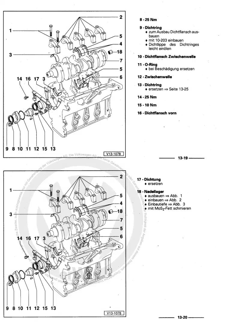
833.3 Renewing needle bearing in crankshaft
833.4 Measuring axial clearance of crankshaft
853.5 Measuring radial clearance of crankshaft
864 Pistons and conrods
874.1 Assembly overview - pistons and conrods
874.2 Removing and installing pistons
904.3 Measuring piston projection at TDC
924.4 Checking pistons and cylinder bores
944.5 Separating new conrod
974.6 Checking radial clearance of conrods
974.7 Removing and installing oil spray jets
98Cylinder head, valve gear
991 Cylinder head
991.1 Assembly overview - cylinder head
991.2 Assembly overview - camshaft housing
1011.3 Assembly overview - cylinder head cover
1031.4 Removing and installing cylinder head
1051.5 Removing and installing cylinder head cover
1111.6 Removing and installing injector seals
1121.7 Removing and installing camshaft housing
1131.8 Checking compression
1182 Toothed belt drive
1212.1 Assembly overview - toothed belt cover
1212.2 Assembly overview - toothed belt
1212.3 Removing and installing toothed belt guard
1232.4 Removing and installing toothed belt
1282.5 Removing toothed belt from camshaft
1363 Valve gear
1443.1 Assembly overview - valve gear
1443.2 Measuring axial play of camshaft
1463.3 Removing and installing camshaft oil seal
1473.4 Checking hydraulic compensation elements
1493.5 Removing and installing valve stem seals
1503.6 Removing and installing toothed belt pulley
1584 Inlet and exhaust valves
1604.1 Checking valve guides
1604.2 Checking valves
1614.3 Valve dimensions
161Lubrication
1621 Sump, oil pump
1621.1 Assembly overview - sump/oil pump
1621.2 Engine oil:
1651.3 Removing and installing lower part of sump
1651.4 Removing and installing upper part of sump
1681.5 Removing and installing oil pump
1711.6 Removing and installing oil level and oil temperature sender G266
1711.7 Removing and installing toothed belt for oil pump
1732 Engine oil cooler
1743 Oil filter, oil pressure switch
1753.1 Assembly overview - oil filter housing, oil pressure switch
1753.2 Assembly overview - oil pressure switches/oil pressure control
1773.3 Checking oil pressure
1783.4 Removing and installing oil filter housing
1783.5 Removing and installing oil pressure regulating valve N428
1793.6 Removing and installing oil pressure sender G10
1803.7 Removing and installing piston cooling jet control valve N522
1824 Oil circuit
1844.1 Assembly overview - oil circuit
1844.2 Removing and installing oil supply line
1844.3 Removing and installing oil return line for turbocharger
186Cooling
1881 Cooling system/coolant
1881.1 Checking cooling system for leaks
1881.2 Draining and adding coolant
1901.3 Checking filling quality
2042 Coolant pump, regulation of cooling system
2072.1 Assembly overview - coolant pump, thermostat
2072.2 Assembly overview - electric coolant pump
2092.3 Assembly overview - coolant temperature sender
2102.4 Removing and installing coolant pump
2112.5 Removing and installing thermostat
2122.6 Removing and installing coolant temperature sender G62
2142.7 Removing and installing engine outlet coolant temperature sender G82
2142.8 Removing and installing coolant regulating valve N515
2152.9 Removing and installing auxiliary pump for heating V488
2162.10 Removing and installing charge air cooling pump V188
2182.11 Removing and installing coolant temperature sender for charge air cooler G1130
2203 Coolant pipes
2223.1 Assembly overview - coolant pipes
2223.2 Removing and installing coolant pipes
2224 Radiator, radiator fan
2274.1 Assembly overview - radiator, radiator fan
2274.2 Assembly overview – radiator cowl and radiator fan
2294.3 Removing and installing radiator
2294.4 Removing and installing cooler for charge air cooling circuit
2314.5 Removing and installing radiator cowl
2344.6 Removing and installing radiator fan VX57
2354.7 Removing and installing radiator fan 2 V177
236Turbocharging/supercharging
2381 Turbocharger
2381.1 Assembly overview - turbocharger
2381.2 Removing and installing turbocharger
2411.3 Removing and installing connection for turbocharger
2432 Charge air system
2452.1 Assembly overview - charge air system
2452.2 Checking charge air cooler for leaks
2452.3 Removing and installing charge air cooler
2492.4 Removing and installing charge pressure sender GX26
2492.5 Checking charge air system for leaks
2502.6 Removing and installing air intake pipe
253Mixture preparation - injection
2551 Injection system
2551.1 Filling/bleeding fuel system
2551.2 Checking fuel system for leaks
2552 Injectors/high-pressure accumulator (rail)
2572.1 Assembly overview - injectors
2572.2 Assembly overview - fuel rail
2582.3 Adapting correction values for injectors
2602.4 Testing injectors
2612.5 Checking return flow rate of injectors with engine running
2612.6 Checking return flow rate of injectors at starter speed
2642.7 Testing jammed-open injectors
2662.8 Removing and installing injectors
2682.9 Removing and installing high-pressure lines
2712.10 Removing and installing fuel rail
2763 Air filter
2793.1 Assembly overview - air filter housing
2793.2 Removing and installing air filter housing
2813.3 Removing and installing air guide on lock carrier
2814 Intake manifold
2834.1 Assembly overview – intake manifold
2834.2 Removing and installing intake manifold
2874.3 Removing and installing throttle valve module GX3
2905 Senders and sensors
2935.1 Removing and installing fuel pressure regulating valve N276
2935.2 Checking fuel pressure regulating valve N276
2955.3 Removing and installing fuel pressure sender G247
2975.4 Removing and installing pressure differential sender G505
2985.7 Removing and installing control unit for NOx sender GX30
3015.8 Removing and installing air mass measurement module GX35
3025.9 Removing and installing control unit 2 for NOx sender GX46
3045.10 Removing and installing control unit 3 for NOx sender GX50
3065.11 Removing and installing control unit 1 for particulate sensor GX52
3076 Engine control unit
3106.1 Removing and installing engine control unit J623
3107 High-pressure pump
3127.1 Assembly overview - high-pressure pump
3127.2 Removing and installing high-pressure pump
3128 Lambda probe
3188.1 Assembly overview - Lambda probe
3188.2 Removing and installing Lambda probe 1 before catalytic converter GX10
320Exhaust system
3221 Exhaust pipes and silencers
3221.1 Assembly overview – silencers
3221.2 Assembly overview - front exhaust pipe
3241.3 Removing and installing front exhaust pipe
3261.4 Separating exhaust pipes from silencers
3281.5 Removing and installing silencer
3291.6 Renewing exhaust pipes
3331.7 Aligning exhaust system free of stress
3331.8 Checking exhaust system for leaks
3341.9 Installation position of clamp
3352 Emission control
3362.1 Assembly overview – emission control
3362.2 Removing and installing emission control module
3382.3 Removing and installing exhaust flap control unit J883
3443 SCR system (selective catalytic reduction)
3473.1 Assembly overview – reducing agent tank
3473.2 Assembly overview - reducing agent supply line
3483.3 Assembly overview - delivery module for reducing agent
3493.4 Removing and installing reducing agent tank
3503.5 Removing and installing filler pipe for reducing agent tank
3523.6 Removing and installing front section of reducing agent supply line
3543.7 Removing and installing middle section of reducing agent supply line
3583.8 Removing and installing rear section of reducing agent supply line
3603.9 Removing and installing delivery unit for reducing agent metering system GX19
3623.10 Removing and installing injector for reduction agent N474
3633.11 Removing and installing control unit for reducing-agent heater J891
3663.12 Draining reducing agent tank
3663.13 SCR - resetting learnt values
3683.14 Removing and installing injector 2 for reducing agent N758
3684 Exhaust gas temperature regulation
3714.1 Assembly overview – exhaust gas temperature regulation
3714.2 Removing and installing exhaust gas temperature sender 1 G235
3724.3 Removing and installing exhaust gas temperature sender 2 G448
3744.4 Removing and installing exhaust gas temperature sender 3 G495
3754.5 Removing and installing exhaust gas temperature sender 4 G648
3775 Exhaust gas recirculation
3805.1 Assembly overview – exhaust gas recirculation
3805.2 Removing and installing exhaust gas recirculation cooler
3815.3 Checking exhaust gas recirculation cooler for leaks
3835.4 Removing and installing exhaust gas recirculation valve 1 GX5
3875.5 Removing and installing exhaust gas recirculation valve 2 GX6
3885.6 Removing and installing exhaust gas recirculation temperature sensor G98
389Glow plug system
3921 Glow plug system
3921.1 Assembly overview – glow plug system
3921.2 Removing and installing glow plug
3931.3 Removing and installing automatic glow period control unit J179
3961.4 Removing and installing Hall sender G40
3961.5 Removing and installing engine speed sender G28
397