Technical data
11 Safety information
11.1 Safety regulations for working on fuel supply
11.2 Safety measures when working on vehicles with a start/stop system
21.4 Safety precautions when working on the cooling system
21.5 Safety precautions when working on SCR system
21.6 Safety precautions when working on exhaust system
42 Identification
52.1 Engine number/engine data
53 Repair notes
73.1 Rules for cleanliness
73.2 General information
73.3 General repair instructions
83.4 Adapting after component replacement
93.5 Foreign objects in engine
93.6 Contact corrosion
93.7 Routing and attachment of lines
103.8 Fitting radiator and condensers
103.9 Checking vacuum system
103.10 Nuts and bolts
113.11 Identification labels
113.12 Using impact drivers
113.13 Checking fuel system for leaks
124 Technical data
144.1 Coolant
15Removing and installing engine
171 Removing and installing engine
171.1 Removing engine
171.2 Separating engine and gearbox
311.3 Securing engine on engine and gearbox support
361.4 Installing engine
382 Assembly mountings
432.1 Assembly overview – assembly mountings
432.2 Removing and installing engine mounting
452.3 Removing and installing gearbox mounting
472.4 Removing and installing pendulum support
502.5 Supporting engine in installation position
502.6 Adjusting assembly mountings
562.7 Checking adjustment of assembly mountings
593 Engine cover panel
603.1 Removing and installing engine cover
60Crankshaft group
611 Cylinder block (pulley end)
611.1 Assembly overview - cylinder block (pulley end)
611.2 Assembly overview - sealing flange, belt pulley end
641.3 Removing and installing poly-V belt
651.4 Removing and installing tensioner for poly V-belt
661.5 Removing and installing vibration damper
671.6 Removing and installing bracket for ancillaries
681.7 Removing and installing engine support
701.8 Removing and installing sealing flange on pulley end
711.9 Renewing caps in cylinder block (pulley end)
752 Cylinder block, gearbox end
772.1 Assembly overview - cylinder block, gearbox end
772.2 Removing and installing flywheel
782.3 Removing and installing sealing flange on gearbox side
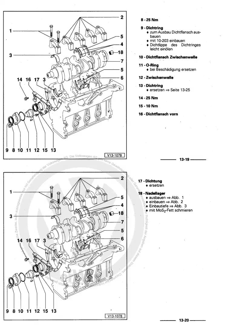
803 Crankshaft
1023.1 Assembly overview - crankshaft
1023.2 Crankshaft dimensions
1033.3 Measuring axial clearance of crankshaft
1043.4 Renewing needle bearing in crankshaft
1054 Pistons and conrods
1084.1 Assembly overview - pistons and conrods
1084.2 Removing and installing pistons
1114.3 Measuring piston projection at TDC
1134.4 Separating new conrod
1154.5 Checking pistons and cylinder bores
1164.6 Checking radial clearance of conrods
118Cylinder head, valve gear
1191 Cylinder head
1191.1 Assembly overview - cylinder head
1191.2 Assembly overview - cylinder head cover
1231.3 Removing and installing cylinder head
1251.4 Removing and installing cylinder head cover
1361.5 Removing and installing injector seals
1371.6 Removing and installing camshaft housing
1381.7 Checking compression
1452 Toothed belt drive
1482.1 Assembly overview - toothed belt cover
1482.2 Assembly overview - toothed belt
1482.3 Removing and installing toothed belt guard
1502.4 Removing and installing toothed belt
1552.5 Removing toothed belt from camshaft
1693 Valve gear
1753.1 Assembly overview - valve gear
1753.2 Measuring axial play of camshaft
1793.3 Removing and installing camshaft oil seal
1793.4 Removing and installing camshaft adjuster
1823.5 Removing and installing camshaft control valve 1 N205
1853.6 Checking hydraulic compensation elements
1863.7 Removing and installing valve stem oil seals
1873.8 Removing and installing control valve for the camshaft adjuster
1974 Inlet and exhaust valves
2014.1 Checking valve guides
2014.2 Checking valves
2024.3 Valve dimensions
202Lubrication
2031 Sump, oil pump
2031.1 Assembly overview - sump/oil pump
2031.2 Engine oil:
2091.3 Removing and installing sump
2091.4 Removing and installing lower part of sump
2131.5 Removing and installing upper part of sump
2171.6 Removing and installing oil pump
2221.7 Removing and installing oil level and oil temperature sender G266
2232 Engine oil cooler
2263 Oil filter, oil pressure switch
2273.1 Assembly overview - oil filter housing, oil pressure switch
2273.2 Removing and installing oil pressure switch F1
2293.3 Removing and installing oil pressure switch for reduced oil pressure F378
2313.4 Checking oil pressure
2333.5 Removing and installing oil filter housing
2343.6 Removing and installing oil pressure regulating valve N428
237Cooling
2381 Cooling system/coolant
2381.1 Connection diagram - coolant hoses
2381.2 Assembly overview – coolant expansion tank
2421.3 Checking cooling system for leaks
2431.4 Draining coolant
2471.5 Filling with coolant
2501.6 Checking filling quality
2621.7 Checking electric vacuum pump VAS 6096/2
2651.8 Flushing cooling system
2661.9 Flushing cooling system, quick reference guide
2891.10 Removing and installing coolant expansion tank
2902 Coolant pump, regulation of cooling system
2932.1 Assembly overview - coolant pump, thermostat
2932.2 Assembly overview - electric coolant pump
2972.3 Assembly overview - coolant temperature sender
3032.4 Removing and installing electric coolant pump
3062.5 Removing and installing coolant pump
3242.6 Removing and installing thermostat
3252.7 Checking thermostat
3292.8 Removing and installing coolant valve for cylinder head N489
3292.9 Removing and installing coolant temperature sender G62
3302.10 Removing and installing radiator outlet coolant temperature sender G83
3313 Coolant pipes
3343.1 Assembly overview - coolant pipes
3343.2 Removing and installing coolant pipes
3364 Radiator, radiator fan
3554.1 Assembly overview - radiator/radiator fan
3554.2 Assembly overview – radiator cowl and radiator fan
3584.3 Removing and installing radiator
3604.4 Removing and installing water radiator for charge air cooling circuit
3624.5 Removing and installing radiator cowl
3674.6 Removing and installing radiator fan
370Turbocharging/supercharging
3721 Turbocharger
3721.1 Assembly overview - turbocharger
3721.2 Removing and installing turbocharger
3811.3 Renewing vacuum unit for turbocharger
3991.4 Removing and installing connection for turbocharger
4082 Charge air system
4102.1 Assembly overview - charge air system
4102.2 Assembly overview - charge-air hose connections
4122.3 Removing and installing charge pressure sender G31
4132.4 Checking charge air system for leaks
4142.5 Removing and installing air intake pipe
4172.6 Checking charge air cooler for leaks
418Mixture preparation - injection
4241 Injection system
4241.1 Schematic overview - fuel system
4241.2 Overview of fitting locations - injection system
4251.3 Filling/bleeding fuel system
4331.4 Checking fuel system for leaks
4342 Vacuum system
4352.1 Connection diagram – vacuum system
4352.2 Checking vacuum system
4363 Injectors/high-pressure accumulator (rail)
4373.1 Assembly overview - injectors
4373.2 Assembly overview - fuel rail
4393.3 Adapting correction values for injectors
4403.4 Testing injectors
4413.5 Checking return flow rate of injectors with engine running
4423.6 Checking return flow rate of injectors at starter speed
4453.7 Checking open injectors
4473.8 Removing and installing injectors
4503.9 Removing and installing high-pressure lines
4533.10 Removing and installing fuel rail
4574 Air filter
4614.1 Assembly overview - air filter housing
4614.2 Removing and installing air filter housing
4634.3 Removing and installing air guide on lock carrier
4655 Intake manifold
4665.1 Assembly overview – intake manifold
4665.2 Removing and installing intake manifold
4695.3 Removing and installing throttle valve module J338
4746 Senders and sensors
4776.1 Removing and installing fuel pressure regulating valve N276
4776.2 Checking fuel pressure regulating valve N276
4846.3 Removing and installing fuel pressure sender G247
4866.4 Removing and installing air mass meter G70/intake air temperature sender G42
4876.5 Removing and installing pressure differential sender G505
4896.6 Removing and installing exhaust gas pressure sensor 1 G450
4926.9 Removing and installing fuel temperature sender G81
4946.10 Removing and installing control unit for NOx sender GX30
4967 Engine control unit
5017.1 Assembly overview – engine/motor control unit
5017.2 Removing and installing engine control unit J623
5017.3 Removing and installing engine (motor) control unit J623 with protective housing
5038 High-pressure pump
5098.1 Assembly overview - high-pressure pump
5098.2 Removing and installing high-pressure pump
5109 Lambda probe
5149.1 Assembly overview - Lambda probe
5149.2 Removing and installing Lambda probe
516Exhaust system
5201 Exhaust pipes and silencers
5201.1 Assembly overview – silencers
5201.2 Assembly overview - front exhaust pipe
5201.3 Removing and installing front exhaust pipe
5221.4 Removing and installing silencer
5231.5 Removing and installing front exhaust pipe bracket
5251.6 Aligning exhaust system free of stress
5261.7 Checking exhaust system for leaks
5271.8 Installation position of clamp
5271.9 Align end exhaust pipes
5292 Emission control
5302.1 Assembly overview – emission control
5302.2 Removing and installing catalytic converter
5342.3 Removing and installing particulate filter
5362.4 Removing and installing emission control module
5362.5 Removing and installing exhaust flap control unit J883
5473 SCR system (selective catalytic reduction)
5493.1 Assembly overview – reducing agent tank
5493.2 Assembly overview - reducing agent supply line
5513.3 Assembly overview - delivery module for reducing agent
5523.4 Removing and installing reducing agent tank
5533.5 Removing and installing front section of reducing agent supply line
5563.6 Removing and installing delivery module for reducing agent
5633.7 Removing and installing injector for reduction agent N474
5653.8 Removing and installing control unit for reducing-agent heater J891
5683.9 Assembly overview - injector for reducing agent
5683.10 Draining reducing agent tank
5703.11 Removing and installing rear section of reducing agent supply line
5733.12 Removing and installing filler pipe for reducing agent tank
5743.13 Disconnecting reducing agent supply line
5763.14 SCR - resetting learnt values
5794 Exhaust gas temperature regulation
5814.1 Assembly overview – exhaust gas temperature regulation
5814.2 Removing and installing exhaust gas temperature sender 1 G235
5834.3 Removing and installing exhaust gas temperature sender 2 G448
5884.4 Removing and installing exhaust gas temperature sender 3 G495
5904.5 Removing and installing exhaust gas temperature sender 4 G648
5925 Exhaust gas recirculation
5955.1 Assembly overview – exhaust gas recirculation
5955.2 Assembly overview - exhaust gas recirculation valve 1 GX5
6005.3 Removing and installing exhaust gas recirculation cooler
6015.4 Removing and installing exhaust gas recirculation valve 1 GX5
6095.5 Removing and installing exhaust gas recirculation valve 2 GX6
6105.6 Removing and installing exhaust gas recirculation temperature sensor G98
6115.7 Checking exhaust gas recirculation cooler for leaks
615Glow plug system
6211 Glow plug system
6211.1 Assembly overview – glow plug system
6211.2 Removing and installing glow plug
6231.3 Removing and installing automatic glow period control unit J179
6261.4 Removing and installing Hall sender G40
6271.5 Removing and installing engine speed sender G28
627