THE CAR REPAIR SHOP
0
Home » Manuals » Heating, air conditioner
  • Examplepage for repair manual Heating, air conditioner
  • Examplepage for repair manual 2 Heating, air conditioner
  • Examplepage for repair manual 3 Heating, air conditioner
  • Examplepage for repair manual Heating, air conditioner
  • Examplepage for repair manual 2 Heating, air conditioner
  • Examplepage for repair manual 3 Heating, air conditioner

Heating, air conditioner

For EOS

Original Volkswagen repair manual


12,61 €7% VAT incl.

  • Deutsch
  • English

Immediately available for download

Language: English

Digital PDF file

4.442 KB

145 Sites

Detailed technical data

Immediately readable

This repair manual contains: Heater, Control motors, Air duct, Operating and display unit, Other controlling and regulating components, Overview of fitting locations - air conditioning system, Refrigerant circuit, Air conditioner compressor and Front heater and air conditioning unit. Show more
Secure Payment via PayPal, credit card, direct debit and more
PayPal Logo SEPA Lastschrift Logo Giropay Logo Sofort Überweisung Logo

Repair manual EOS Heating, air conditioner PDF download has the following content:

Chapter overview

  • Technical data
    1
  • 1 Safety information
    1
  • 1.1 Safety precautions when working on air conditioning systems
    1
  • 1.2 Safety measures when working on vehicles with a start/stop system
    1
  • 1.3 Safety precautions when working on the cooling system
    1
  • 2 General information
    3
  • 2.1 Notes concerning odours in air conditioned vehicles
    3
  • 2.2 Notes for vehicles with start-stop system
    3
  • 3 Repair instructions
    4
  • 3.1 Working on refrigerant circuit
    4
  • 3.2 Refrigerant circuit seals
    4
  • 3.3 Notes on control motors
    5
  • 4 Technical data
    11
  • 4.1 Capacities for refrigerant R134a
    11
  • 4.2 Refrigerant oil
    11
  • 4.3 Oil distribution
    11
  • Heating
    12
  • 1 Heater
    12
  • 1.1 Removing and installing fresh air blower V2
    12
  • 1.2 Removing and installing fresh air blower series resistor with overheating fuse N24
    13
  • 1.3 Removing and installing heater unit
    13
  • 1.4 Dismantling and assembling heater unit
    17
  • 2 Control motors
    20
  • 3 Air duct
    21
  • 4 Operating and display unit
    22
  • 5 Other controlling and regulating components
    23
  • Air conditioning system
    24
  • 1 Overview of fitting locations - air conditioning system
    24
  • 2 Refrigerant circuit
    30
  • 2.1 System overview - refrigerant circuit
    30
  • 2.2 Removing and installing high-pressure sender G65
    31
  • 2.3 Removing and installing expansion valve
    32
  • 2.4 Removing and installing condenser
    35
  • 2.5 Removing and installing receiver
    38
  • 2.6 Removing and installing desiccant bag or cartridge
    39
  • 2.7 Removing and installing evacuating and charging valves on low and high-pressure side
    41
  • 3 Air conditioner compressor
    43
  • 3.1 Assembly overview - drive unit of air conditioner compressor
    43
  • 3.2 Removing and installing air conditioner compressor
    43
  • 3.3 Checking high-pressure safety valve on air conditioner compressor
    48
  • 3.4 Ancillary bracket for air conditioner compressor
    49
  • 4 Front heater and air conditioning unit
    61
  • 4.1 Assembly overview – heater and air conditioning unit
    61
  • 4.2 Removing and installing heater and air conditioning unit
    66
  • 4.3 Removing and installing evaporator
    71
  • 4.4 Dismantling and assembling evaporator housing
    72
  • 4.5 Removing fresh air blower V2 with fresh air blower control unit J126
    73
  • 4.6 Removing and installing evaporator output temperature sender G263
    74
  • 4.7 Removing and installing evaporator temperature sensor G308
    75
  • 4.8 Removing and installing dust and pollen filter
    75
  • 4.9 Removing and installing heat exchanger
    76
  • 4.10 Removing and installing auxiliary air heater element Z35
    80
  • 4.11 Checking condensation drain
    83
  • 4.12 Removing and installing glove box cooling
    83
  • 5 Air duct
    85
  • 5.1 Removing and installing fresh air intake
    85
  • 5.2 Removing and installing air intake duct
    86
  • 5.3 Removing vents
    87
  • 5.4 Checking forced ventilation for passenger compartment
    89
  • 5.5 Removing and installing forced ventilation for passenger compartment
    89
  • 6 Operating and display unit
    91
  • 6.1 Overview of operating and display unit
    91
  • 6.2 Removing and installing operating and display unit
    102
  • 6.3 Multi-pin connector pin assignment on back of operating and display unit
    103
  • 7 Control motors
    110
  • 7.1 Removing and installing temperature flap control motor V68
    110
  • 7.2 Removing and installing centre flap control motor V70
    112
  • 7.3 Removing and installing air flow flap control motor V71
    113
  • 7.4 Removing and installing defroster flap control motor V107
    117
  • 7.5 Removing and installing air recirculation flap control motor V113
    119
  • 7.7 Removing and installing left temperature flap control motor V158
    124
  • 7.8 Removing and installing right temperature flap control motor V159
    126
  • 7.9 Removing and installing fresh air/air recirculation, air flow flap control motor V425
    128
  • 7.10 Removing and installing front air distribution flap control motor V426
    130
  • 7.11 Removing and installing air distribution flap control motor V428
    131
  • 7.12 Removing and installing air distribution flap actuator
    132
  • 7.13 Removing and installing flexible shaft, vehicles up to week 21/08
    133
  • 8 Other controlling and regulating components
    135
  • 8.1 Removing and installing ambient temperature sensor G17
    135
  • 8.3 Principle of operation of air quality sensor G238
    136
  • 8.4 Removing and installing air quality sensor G238 , vehicles from week 22/08
    137
  • 8.5 Removing and installing left vent temperature sender G150
    138
  • 8.6 Removing and installing right vent temperature sender G151
    139
  • 8.7 Removing and installing centre vent temperature sender G191
    139
  • 8.8 Removing and installing footwell vent temperature sender G192
    139
  • 8.9 Removing and installing left footwell vent temperature sender G261
    140
  • 8.10 Removing and installing right footwell vent temperature sender G262
    140
Manufacturer's designation Heating, air conditioner
Manufacturer Volkswagen
Suitable for EOS (2006)
Suitable car types 1F
Category Reparaturanleitung

There are no reviews for this product at the moment.

Similar repair manuals

Body Repairs

Examplepage for repair manual Body Repairs

For EOS (2006)

15,82 € Details

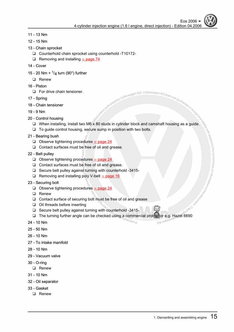
4-cylinder injection engine (1.6 l engine, direct injection)

Examplepage for repair manual 4-cylinder injection engine (1.6 l engine, direct injection)

For EOS (2006)

13,70 € Details

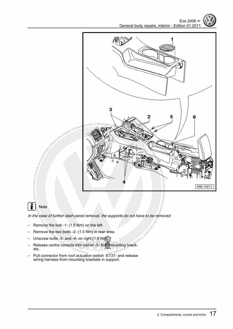
General body repairs, interior

Examplepage for repair manual General body repairs, interior

For EOS (2006)

16,33 € Details

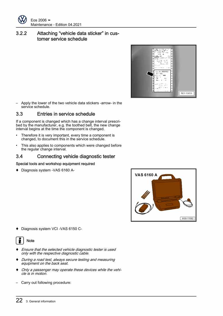
Maintenance

Examplepage for repair manual Maintenance

For EOS (2006)

16,33 € Details

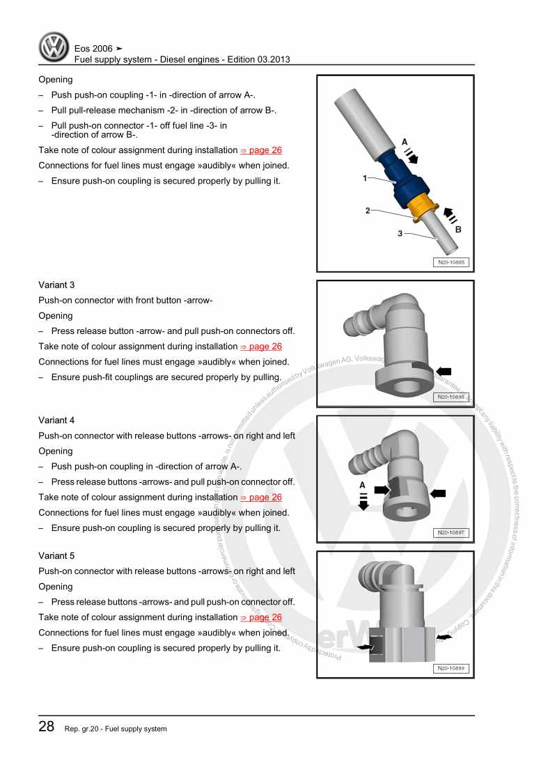
Fuel supply system - Diesel engines

Examplepage for repair manual Fuel supply system - Diesel engines

For EOS (2006)

6,52 € Details

4-cylinder diesel engine (2.0 l engine, 2 valve)

Examplepage for repair manual 4-cylinder diesel engine (2.0 l engine, 2 valve)

For EOS (2006)

13,85 € Details

Running gear, axles, steering

Examplepage for repair manual Running gear, axles, steering

For EOS (2006)

28,09 € Details

Communication

Examplepage for repair manual Communication

For EOS (2006)

13,20 € Details

6-cylinder injection engine

Examplepage for repair manual 6-cylinder injection engine

For EOS (2006)

21,70 € Details

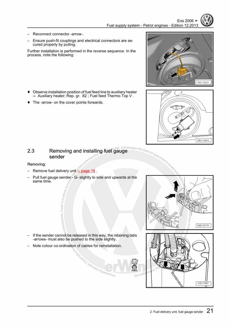
Fuel supply system - Petrol engines

Examplepage for repair manual Fuel supply system - Petrol engines

For EOS (2006)

6,88 € Details

Our Best Sellers

Did you know? We also offer original spare parts.

car part N10638901 Schraube

N10638901

Schraube

2,94 €

Details
car part 8W0807611A Schlieteil

8W0807611A

Schlieteil

66,85 €

Details
car part 0B1409422D Lager

0B1409422D

Lager

76,64 €

Details
car part 4G0919267H Aufnahme

4G0919267H

Aufnahme

21,35 €

Details
car part N904162024PK Schraube

N904162024PK

Schraube

1,29 €

Details

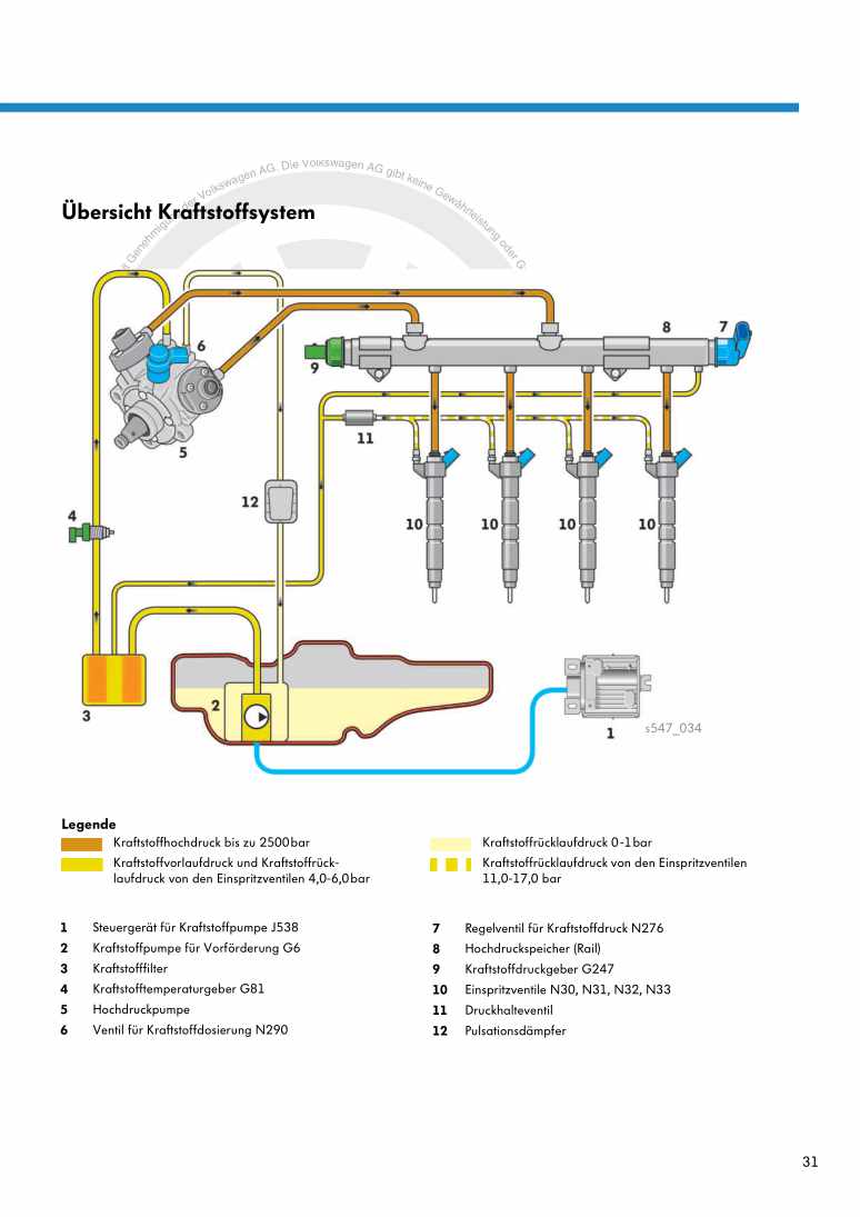
Nr. 547: Der 2,0l-176kW-TDI-Biturbo-Motor der Dieselmotoren-Baureihe EA288

Examplepage for repair manual Nr. 547: Der 2,0l-176kW-TDI-Biturbo-Motor der Dieselmotoren-Baureihe EA288

5,89 € Details

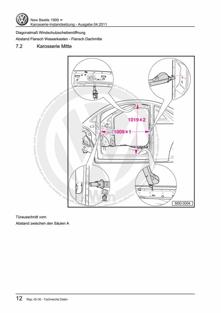
Karosserie-Instandsetzung

Examplepage for repair manual Karosserie-Instandsetzung

For New Beetle / New Beetle (USA) (1998 - 2007) / New Beetle (Europe) (1999 - 2002)

10,12 € Details

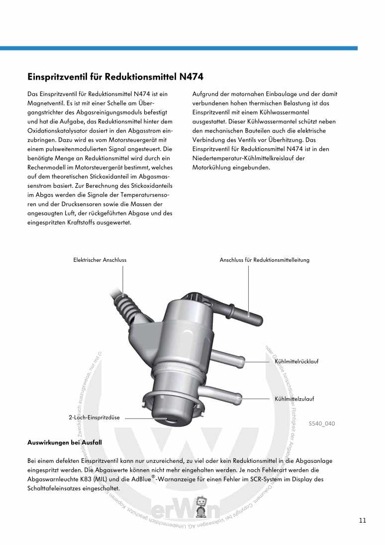
Nr. 540: Das Abgasnachbehandlungssystem Selective-Catalytic-Reduction

Examplepage for repair manual Nr. 540: Das Abgasnachbehandlungssystem Selective-Catalytic-Reduction

5,67 € Details

image/svg+xml About Clonck

Original repair manuals und spare parts

Our repair manuals are original, come directly from Volkswagen and meet the highest quality standards.

In our original parts shop we sell high-quality original spare parts from car manufacturers. Use the search function to enter the desired part number (OE number) and order the required spare part quickly and easily.

Highest quality standards

At Clonck, we want to make car mechanics and car professionals happy. That's why you will only find professional and high-quality repair manuals at Clonck that will help you to repair your vehicle professionally.

Our partners

Autohaus Schmidt GmbH
Automag GmbH Filiale Laim
KFZ-VERLAG GmbH
Zimpel und Franke GmbH

Clonck: The car repair shop - also as app!

Clonck App Logo Play Store

Clonck: Fitting car parts for your car repair

4,5 90

With Clonck you can order the right original spare parts in no time.

  • Add your car model
  • Select assembly group
  • Enter vehicle identification number (VIN)
  • Access to over 5,000 original repair manuals
Start app now
Clonck App Preview Car Mobilephone Carparts