THE CAR REPAIR SHOP
0
Home » Manuals » Auxiliary heater
  • Examplepage for repair manual Auxiliary heater
  • Examplepage for repair manual 2 Auxiliary heater
  • Examplepage for repair manual 3 Auxiliary heater
  • Examplepage for repair manual Auxiliary heater
  • Examplepage for repair manual 2 Auxiliary heater
  • Examplepage for repair manual 3 Auxiliary heater

Auxiliary heater

For CRAFTER / LT 2006>

Original Volkswagen repair manual


13,56 €7% VAT incl.

  • Deutsch
  • English

Immediately available for download

Language: English

Digital PDF file

1.501 KB

158 Sites

Detailed technical data

Immediately readable

This repair manual contains: Hydronic D5WS auxiliary coolant heater, Pre-selection clock E111 of Hydronic D5WS auxiliary coolant heater, Maintenance work on Hydronic D5WS auxiliary coolant heater, Coolant circuit with auxiliary/supplementary heater, Fuel supply to Hydronic D5WS auxiliary coolant heater, Auxiliary air heaters Airtronic D2 and D4S, Maintenance work on auxiliary air heaters Airtronic D2 and D4S and Fuel supply to Airtronic auxiliary air heaters D2 and D4S. Show more
Secure Payment via PayPal, credit card, direct debit and more
PayPal Logo SEPA Lastschrift Logo Giropay Logo Sofort Überweisung Logo

Repair manual CRAFTER / LT 2006> Auxiliary heater PDF download has the following content:

Chapter overview

  • Supplementary heating
    1
  • 1 Hydronic D5WS auxiliary coolant heater
    1
  • 1.1 General information
    1
  • 1.2 Safety precautions
    1
  • 1.3 Rules for cleanliness and important notes
    2
  • 1.4 General notes
    3
  • 1.5 Overview of fitting locations – Hydronic D5WS auxiliary coolant heater
    3
  • 1.6 Assembly overview – Hydronic D5WS auxiliary coolant heater
    4
  • 1.7 Notes on operation of Hydronic D5WS auxiliary coolant heater
    4
  • 1.8 Control and safety devices of Hydronic D5WS auxiliary coolant heater
    5
  • 1.9 Technical data of Hydronic D5WS auxiliary coolant heater
    6
  • 1.10 Type and configuration of the Hydronic D5WS auxiliary coolant heater
    8
  • 1.11 Technical data of the coolant circulation pump V50
    9
  • 2 Pre-selection clock E111 of Hydronic D5WS auxiliary coolant heater
    10
  • 2.1 Operation and function of pre-selection clock E111
    10
  • 2.2 Setting, activating and deactivating pre-selected times
    12
  • 2.3 Removing and installing pre-selection clock E111
    13
  • 2.4 Diagnosis functions of the pre-selection clock E111
    14
  • 2.5 Reading event memory using pre-selection clock E111
    14
  • 2.6 Table of fault codes in event memory (fault codes 000-050)
    15
  • 2.7 Table of fault codes in event memory (fault codes 051-091)
    19
  • 2.8 Unlocking control unit and clearing event memory
    22
  • 3 Maintenance work on Hydronic D5WS auxiliary coolant heater
    23
  • 3.1 Safety precautions
    23
  • 3.2 General information
    24
  • 3.3 Assembly overview - heater unit of Hydronic D5WS auxiliary coolant heater
    24
  • 3.4 Removing and installing heater unit with bracket
    27
  • 3.5 Removing and installing heater unit bracket
    29
  • 3.6 Removing and installing seal (sealing foil)
    30
  • 3.7 Removing and installing exhaust pipe
    31
  • 3.8 Removing and installing blower cover
    31
  • 3.9 Removing and installing housing cover
    32
  • 3.10 Removing and installing auxiliary heater control unit J364
    33
  • 3.11 Removing and installing glow plug for heater Q9
    34
  • 3.12 Removing and installing fuel connection
    36
  • 3.13 Removing and installing flame monitor G64
    37
  • 3.14 Checking flame monitor G64
    40
  • 3.17 Removing and installing combustion air blower V6
    42
  • 3.18 Checking rotation speed of combustion air blower V6
    44
  • 3.19 Removing and installing flame protection mesh
    44
  • 3.20 Removing and installing combustion chamber
    45
  • 3.21 Removing and installing heat exchanger
    47
  • 3.22 Removing and installing remote control receiver for auxiliary coolant heater R149
    48
  • 4 Coolant circuit with auxiliary/supplementary heater
    49
  • 4.1 Coolant hose schematic diagram
    49
  • 5 Fuel supply to Hydronic D5WS auxiliary coolant heater
    57
  • 5.1 Safety precautions
    57
  • 5.2 Rules for cleanliness
    57
  • 5.3 Assembly overview - fuel take-off
    57
  • 5.4 Removing and installing metering pump V54 for Hydronic D5WS
    58
  • 5.5 Removing and installing strainer of metering pump V54
    59
  • 5.6 Prerequisites for checking/measuring fuel delivery rate
    60
  • 5.7 Checking/measuring fuel delivery rate of Hydronic and »D5WS« auxiliary coolant heater
    60
  • 6 Auxiliary air heaters Airtronic D2 and D4S
    62
  • 6.1 General information
    62
  • 6.2 Safety precautions
    62
  • 6.3 Rules for cleanliness
    63
  • 6.4 Overview of auxiliary air heaters installed in vehicle
    63
  • 6.5 Working principles of Airtronic auxiliary air heaters D2 and D4S
    65
  • 6.6 Control and safety devices of auxiliary air heaters Airtronic D2 and D4S
    66
  • 6.7 Fitting location and principle of operation of Airtronic D2 auxiliary air heater
    67
  • 6.8 Fitting location and principle of operation of Airtronic D4S auxiliary air heater
    69
  • 6.9 Technical data of Airtronic D2 auxiliary air heater
    70
  • 6.10 Technical data of Airtronic D4S auxiliary air heater
    72
  • 6.11 Type and version of auxiliary air heaters Airtronic D2 and D4S
    74
  • 6.12 Synchronising remote control
    78
  • 6.13 Setting or changing operating time of auxiliary heater
    79
  • 6.14 Using remote control
    80
  • 7.1 General information
    81
  • 7.4 Removing and installing pre-selection clock E111 with temperature regulator
    84
  • 7.5 Pin assignment on rear of pre-selection clock E111 with temperature regulator
    85
  • 7.6 Diagnosis functions of the pre-selection clock E111
    86
  • 7.7 Reading event memory using pre-selection clock E111
    86
  • 7.10 Unlocking control unit and clearing event memory
    93
  • 8.1 General information
    95
  • 8.4 Removing and installing pre-selection clock E111 with temperature regulator
    98
  • 8.5 Pin assignment on rear of pre-selection clock E111 with temperature regulator
    99
  • 8.6 Diagnosis functions of the pre-selection clock E111
    100
  • 8.7 Reading and erasing event memory using pre-selection clock E111
    101
  • 8.10 Disabling control unit lock
    108
  • 9 Maintenance work on auxiliary air heaters Airtronic D2 and D4S
    110
  • 9.1 Safety precautions
    110
  • 9.2 General information
    111
  • 9.3 Assembly overview - heater unit of Airtronic D2 auxiliary air heater
    111
  • 9.4 Assembly overview - heater unit of Airtronic D4S auxiliary air heater
    113
  • 9.5 Overview of available versions of combustion air blower V6
    114
  • 9.6 Removing and installing heater unit of Airtronic D2 auxiliary air heater
    114
  • 9.9 Removing and installing exhaust pipe of Airtronic D2 auxiliary air heater
    121
  • 9.10 Removing and installing exhaust pipe of Airtronic D4S auxiliary air heater
    121
  • 9.14 Removing and installing air duct of Airtronic D4S auxiliary air heater
    125
  • 9.16 Working principles of auxiliary heater control unit J364
    127
  • 9.17 Removing and installing auxiliary heater control unit J364
    128
  • 9.18 Removing and installing glow plug for heater Q9
    129
  • 9.19 Removing and installing flame protection mesh
    131
  • 9.21 Checking flame monitor G64 and overheating sensor G189
    136
  • 9.22 Removing and installing combustion air blower V6 (combination blower)
    137
  • 9.23 Removing and installing heat exchanger
    140
  • 9.24 Removing and installing combustion chamber
    142
  • 9.25 Ambient temperature sender 2 G249
    145
  • 10 Fuel supply to Airtronic auxiliary air heaters D2 and D4S
    146
  • 10.1 Safety precautions
    146
  • 10.2 Rules for cleanliness
    146
  • 10.3 Assembly overview - fuel take-off
    146
  • 10.4 Removing and installing metering pump V54
    147
  • 10.5 Removing and installing strainer of metering pump V54
    150
  • 10.6 Prerequisites for checking/measuring fuel delivery rate
    150
Manufacturer's designation Auxiliary heater
Manufacturer Volkswagen
Suitable for CRAFTER (2006 - 2007) / LT 2006> (2006 - 2007)
Suitable car types 2F, 2E
Category Reparaturanleitung

There are no reviews for this product at the moment.

Similar repair manuals

Communication

Examplepage for repair manual Communication

For CRAFTER (2006 - 2007) / LT 2006> (2006 - 2007)

14,36 € Details

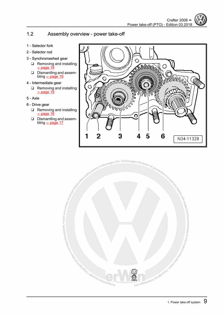
Power take-off (PTO)

Examplepage for repair manual Power take-off (PTO)

For CRAFTER (2006 - 2007) / LT 2006> (2006 - 2007)

5,16 € Details

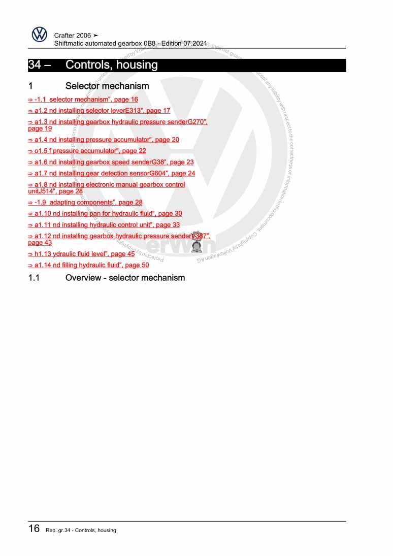
Shiftmatic automated gearbox 0B8

Examplepage for repair manual Shiftmatic automated gearbox 0B8

For CRAFTER (2006 - 2007) / LT 2006> (2006 - 2007)

8,02 € Details

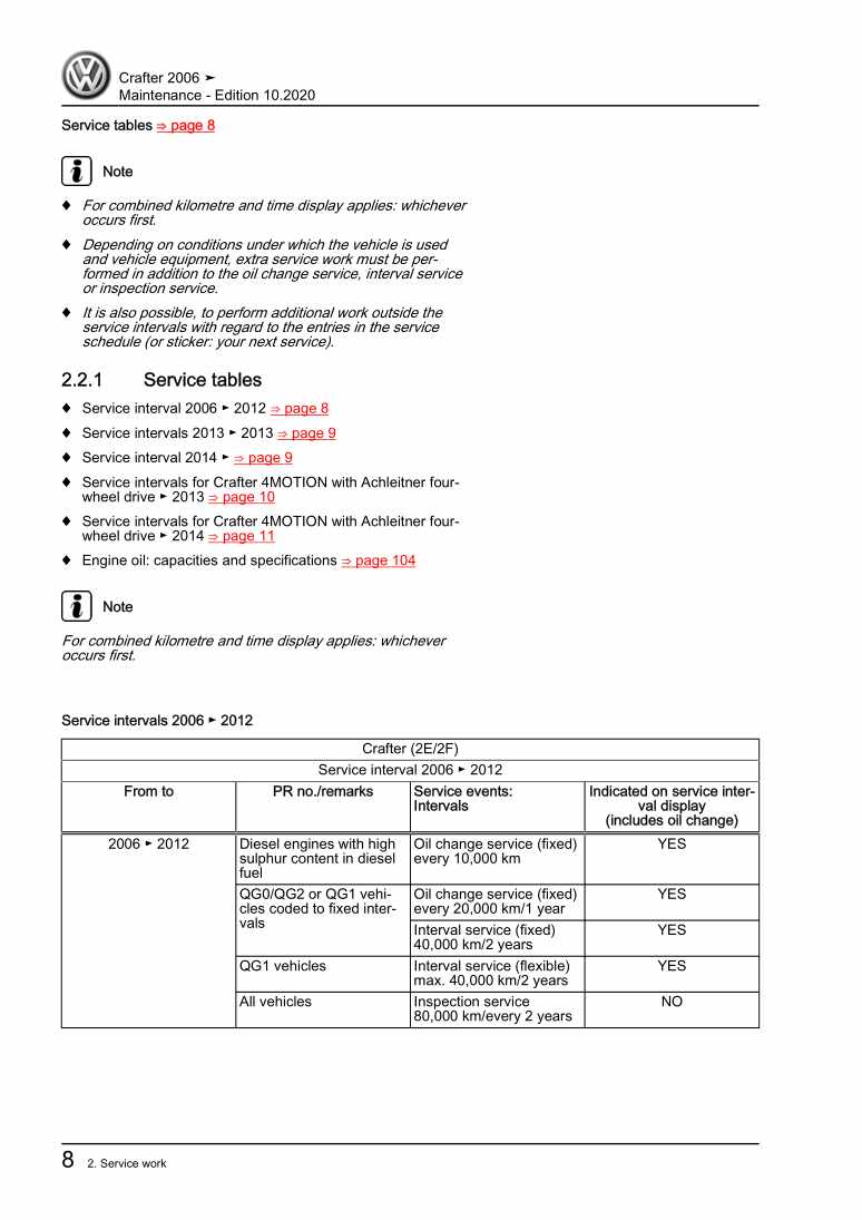
Maintenance

Examplepage for repair manual Maintenance

For CRAFTER (2006 - 2007) / LT 2006> (2006 - 2007)

15,68 € Details

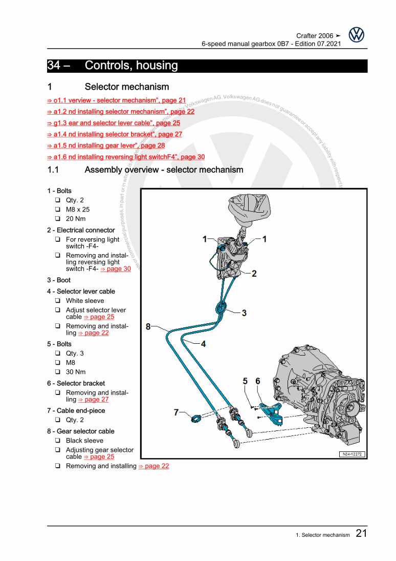
6-speed manual gearbox 0B7

Examplepage for repair manual 6-speed manual gearbox 0B7

For CRAFTER (2006 - 2007) / LT 2006> (2006 - 2007)

10,75 € Details

Wheels and Tyres Guide

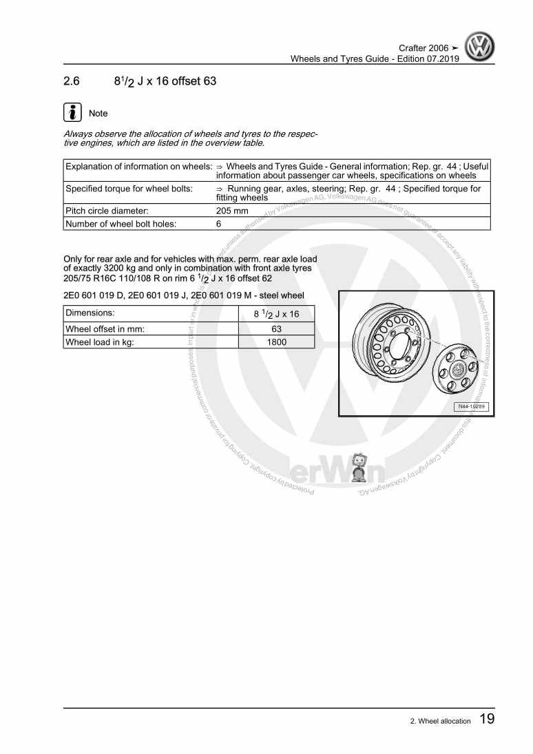
Examplepage for repair manual Wheels and Tyres Guide

For CRAFTER (2006 - 2007) / LT 2006> (2006 - 2007)

4,97 € Details

6-speed manual gearbox 0CB

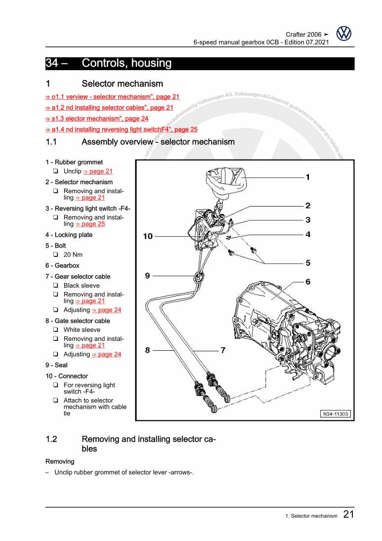
Examplepage for repair manual 6-speed manual gearbox 0CB

For CRAFTER (2006 - 2007) / LT 2006> (2006 - 2007)

11,68 € Details

Fuel supply system - Diesel engines

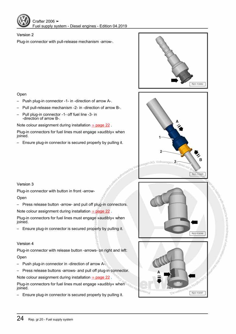
Examplepage for repair manual Fuel supply system - Diesel engines

For CRAFTER (2006 - 2007) / LT 2006> (2006 - 2007)

5,57 € Details

Rear axle and rear final drive

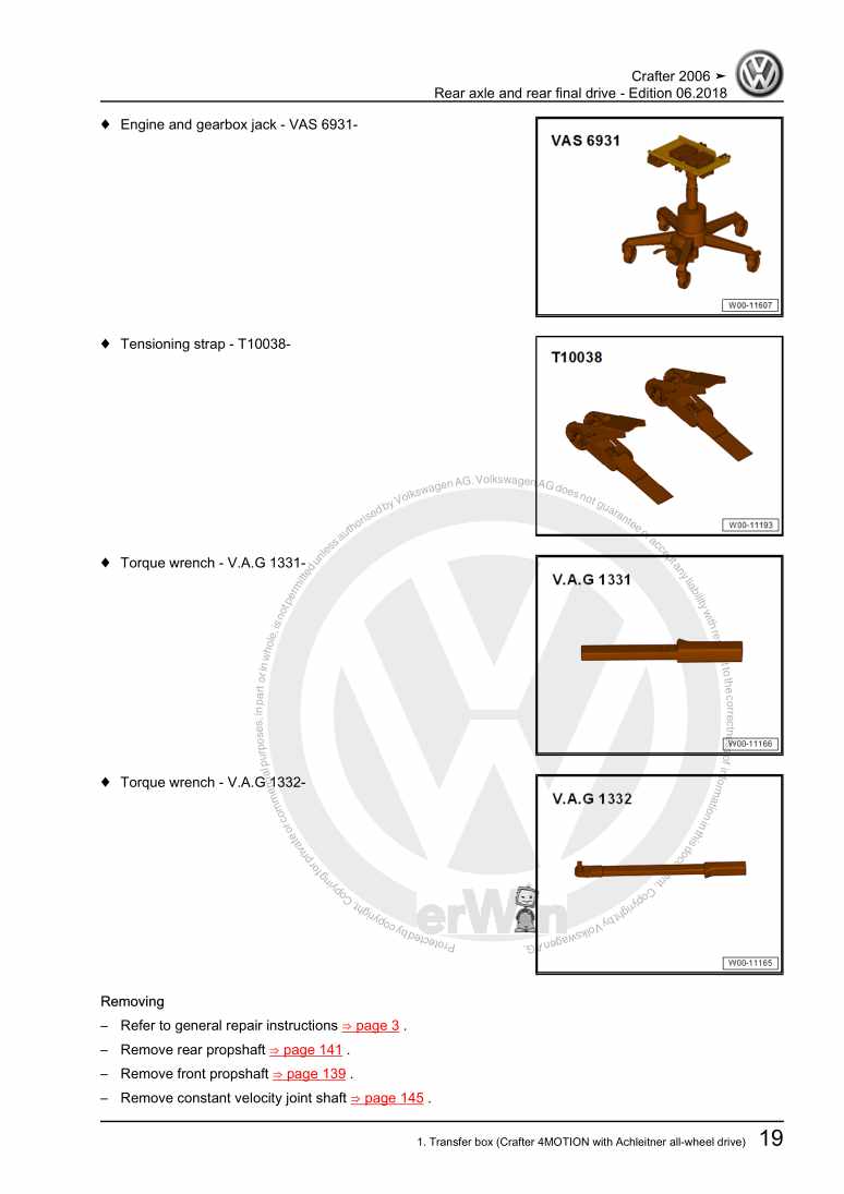
Examplepage for repair manual Rear axle and rear final drive

For CRAFTER (2006 - 2007) / LT 2006> (2006 - 2007)

15,24 € Details

Body Repairs

Examplepage for repair manual Body Repairs

For CRAFTER (2006 - 2007) / LT 2006> (2006 - 2007)

33,67 € Details

Our Best Sellers

Did you know? We also offer original spare parts.

car part N10638901 Schraube

N10638901

Schraube

3,01 €

Details
car part 3AA863324BNV1 Blende

3AA863324BNV1

Blende

14,30 €

Details
car part N10196105 Schraube

N10196105

Schraube

1,11 €

Details
car part 4KE998465C Rep.Satz

4KE998465C

Rep.Satz

30,45 €

Details
car part 0BF598079 Rep.Satz

0BF598079

Rep.Satz

199,12 €

Details

Digijet-Einspritzanlage/ TSZ-H Zündanlage

Examplepage for repair manual Digijet-Einspritzanlage/ TSZ-H Zündanlage

For Polo / Polo Coupe / Polo Steilheck / Polo Stufenheck (1987 - 1994)

6,35 € Details

Nr. 526: Die Dieselmotoren-Baureihe EA288 mit Abgasnorm EU6

Examplepage for repair manual Nr. 526: Die Dieselmotoren-Baureihe EA288 mit Abgasnorm EU6

5,89 € Details

Standheizung, Zusatzheizung

Examplepage for repair manual Standheizung, Zusatzheizung

For Touareg (2011) / Touareg FL (2015 > )

6,64 € Details

image/svg+xml About Clonck

Original repair manuals und spare parts

Our repair manuals are original, come directly from Volkswagen and meet the highest quality standards.

In our original parts shop we sell high-quality original spare parts from car manufacturers. Use the search function to enter the desired part number (OE number) and order the required spare part quickly and easily.

Highest quality standards

At Clonck, we want to make car mechanics and car professionals happy. That's why you will only find professional and high-quality repair manuals at Clonck that will help you to repair your vehicle professionally.

Our partners

Autohaus Schmidt GmbH
Automag GmbH Filiale Laim
KFZ-VERLAG GmbH
Zimpel und Franke GmbH

Clonck: The car repair shop - also as app!

Clonck App Logo Play Store

Clonck: Fitting car parts for your car repair

4,5 90

With Clonck you can order the right original spare parts in no time.

  • Add your car model
  • Select assembly group
  • Enter vehicle identification number (VIN)
  • Access to over 5,000 original repair manuals
Start app now
Clonck App Preview Car Mobilephone Carparts