DER AUTOREPARATUR-SHOP
0
Home » Anleitungen » Heating, air conditioner
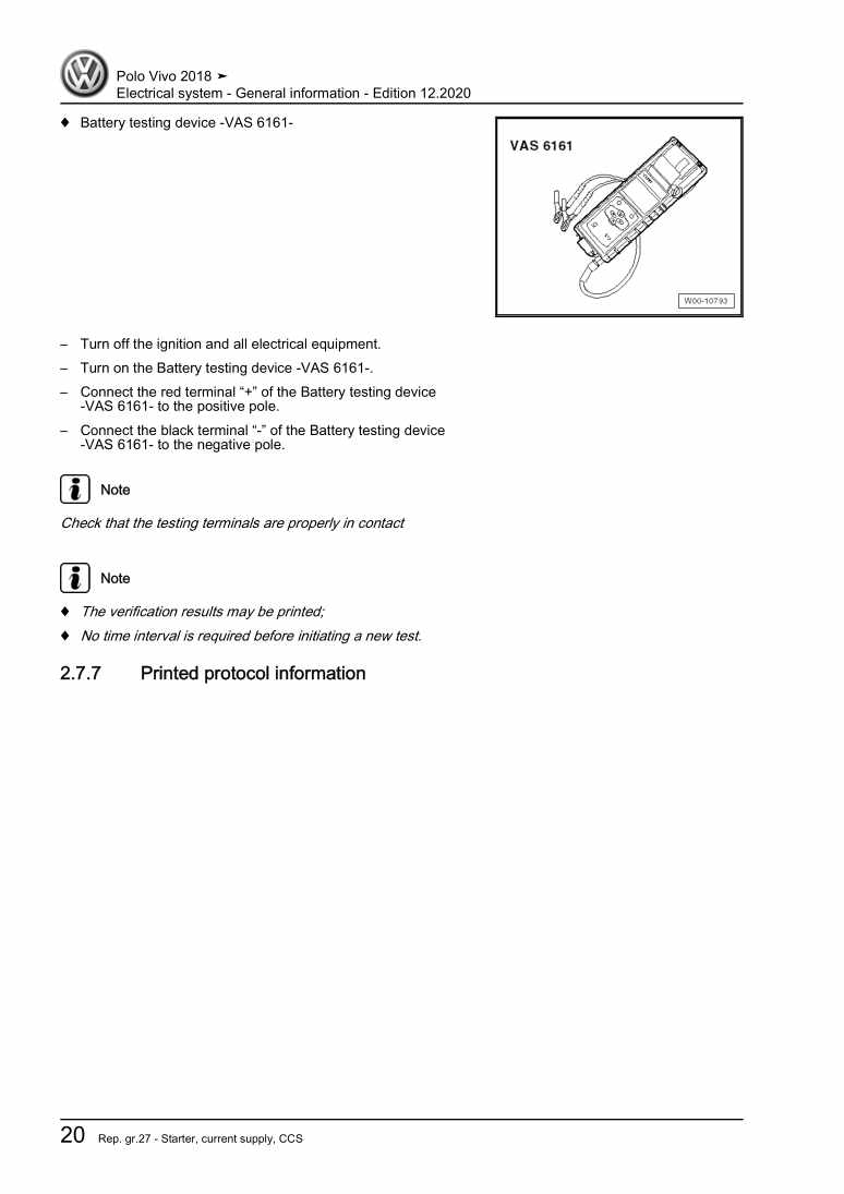
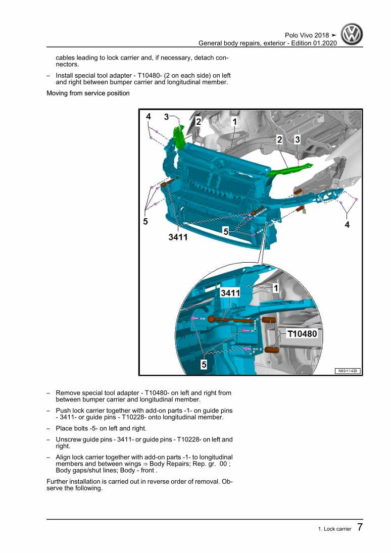
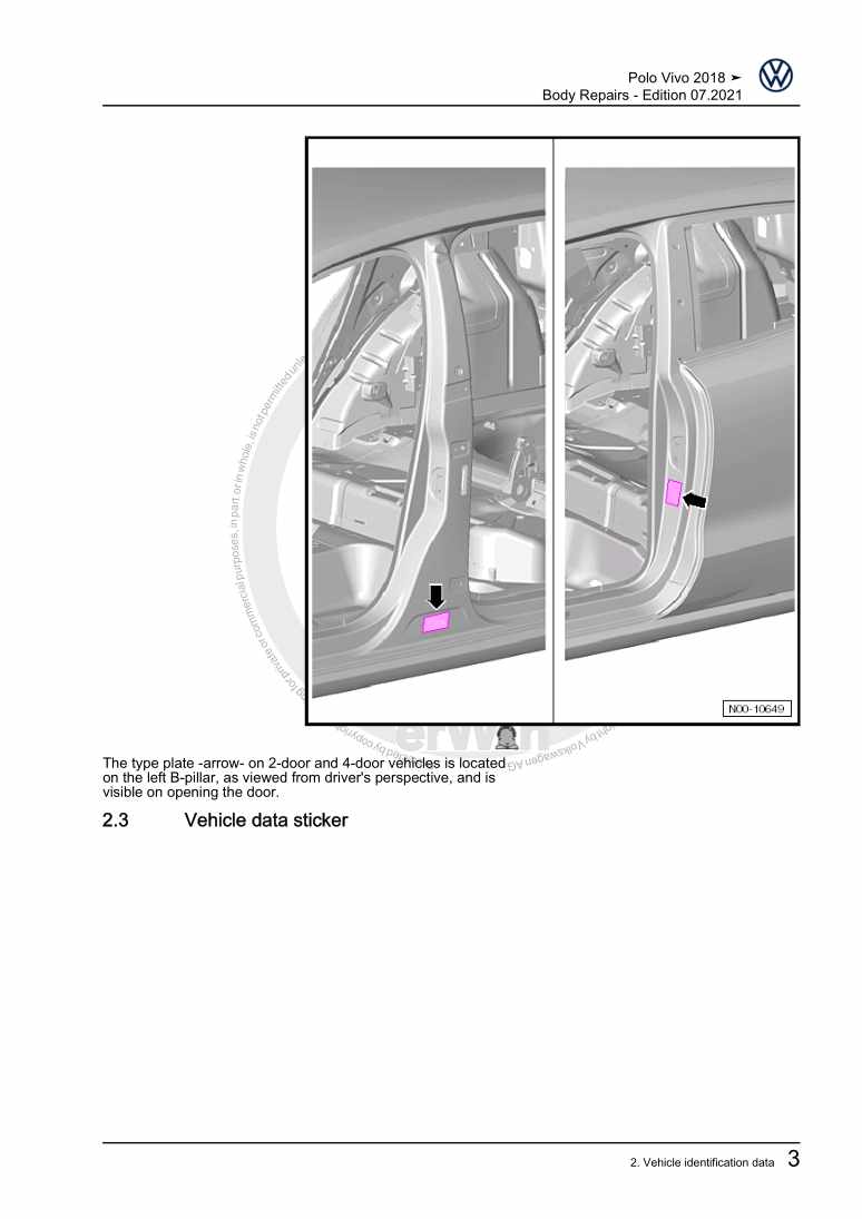
  • Beispielseite für Reparaturanleitung Heating, air conditioner
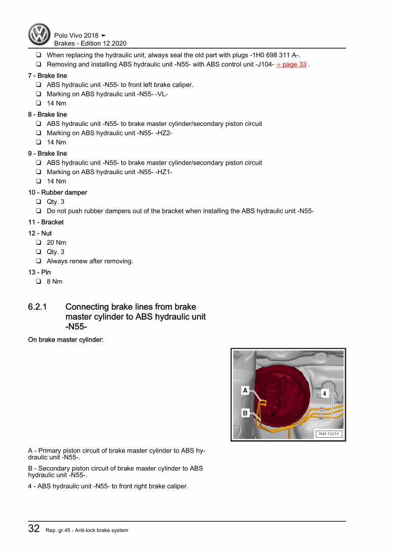
  • Beispielseite für Reparaturanleitung 2 Heating, air conditioner
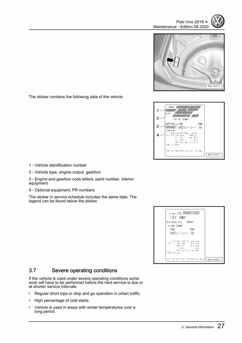
  • Beispielseite für Reparaturanleitung 3 Heating, air conditioner
  • Beispielseite für Reparaturanleitung Heating, air conditioner
  • Beispielseite für Reparaturanleitung 2 Heating, air conditioner
  • Beispielseite für Reparaturanleitung 3 Heating, air conditioner

Heating, air conditioner

Für Polo Vivo

Original VW-Reparaturanleitung


13,56 €inkl. 7% MwSt.

Sofort als Download verfügbar

Sprache: English

Digitale PDF Version

7.049 KB

158 Seiten

Detaillierte technische Daten

Sofort lesbar

Diese Reparaturanleitung umfasst: Overview of fitting locations - heating, Heater unit, Control motors, Air duct, Operating and display unit, Other controlling and regulating components, Overview of fitting locations - air conditioning system, Refrigerant circuit, Air conditioner compressor und Front heater and air conditioning unit. Mehr anzeigen
Sichere Zahlung per PayPal, Kreditkarte, Lastschrift, Sofort-Überweisung oder Giropay
PayPal Logo SEPA Lastschrift Logo Giropay Logo Sofort Überweisung Logo

Reparaturanleitung Polo Vivo Heating, air conditioner pdf Download mit dem Inhalt:

Kapitelübersicht

  • Technical data
    1
  • 1 General notes
    1
  • 1.1 Notes concerning odours in air conditioned vehicles
    1
  • 1.2 Notes for vehicles with a start-stop system
    1
  • 1.3 Notes on repair work to vehicles with air conditioning and on handling refrigerant
    2
  • 1.4 Procedure for checking and adjusting components
    2
  • 1.5 Identification plates
    2
  • 2 Notes on safety
    4
  • 2.1 Safety precautions when handling refrigerants
    4
  • 2.2 Safety measures for when working on vehicles with a start-stop system
    5
  • 3 Repair notes
    6
  • 4 Technical data
    8
  • 4.1 Capacities for refrigerant R134a
    8
  • 4.2 Refrigerant machine oil
    8
  • 4.3 Oil distribution
    9
  • Heating
    10
  • 1 Overview of fitting locations - heating
    10
  • 1.1 Overview of fitting locations - components not located in passenger compartment
    10
  • 2 Heater unit
    15
  • 2.1 Assembly overview – heater unit
    15
  • 2.2 Removing and installing fresh air blower V2
    17
  • 2.3 Removing and installing fresh air blower series resistor with overheating fuse N24
    17
  • 2.4 Removing and installing dust and pollen filter
    17
  • 2.5 Removing and installing heat exchanger
    17
  • 2.6 Removing and installing heater unit
    17
  • 2.7 Dismantling and assembling heater unit
    17
  • 2.8 Checking auxiliary air heater element Z35
    19
  • 2.9 Removing and installing auxiliary air heater element Z35
    19
  • 2.10 Removing and installing flexible shafts
    19
  • 3 Control motors
    20
  • 3.1 Overview of fitting locations - front control motors
    20
  • 3.2 Removing and installing air distribution flap actuator
    21
  • 3.3 Removing and installing temperature flap actuator
    23
  • 3.4 Removing and installing fresh air and air recirculation flap control motor V154
    26
  • 4 Air duct
    27
  • 4.1 Assembly overview - air duct and air distribution in passenger compartment
    27
  • 4.2 Removing and installing centre vent at front
    27
  • 4.3 Removing and installing right or left vent
    27
  • 4.4 Removing and installing driver side footwell vents
    27
  • 4.5 Removing and installing front passenger side footwell vents
    27
  • 4.6 Removing and installing rear air duct
    27
  • 4.7 Checking exhaust ventilation for passenger compartment
    27
  • 4.8 Removing and installing exhaust ventilation for passenger compartment
    28
  • 4.9 Removing and installing fresh air intake
    28
  • 4.10 Removing and installing air duct for defroster vent
    28
  • 4.11 Removing and installing air duct for centre vent
    28
  • 5 Operating and display unit
    29
  • 5.1 Exploded view of fitting locations - operating and display unit
    29
  • 5.2 Removing and installing operating and display unit
    30
  • 6 Other controlling and regulating components
    32
  • 6.1 Removing and installing ambient temperature sensor G17
    32
  • Air conditioning system
    33
  • 1 Overview of fitting locations - air conditioning system
    33
  • 1.1 Overview of fitting locations - components not located in passenger compartment
    33
  • 2 Refrigerant circuit
    47
  • 2.1 System overview - refrigerant circuit
    47
  • 2.2 Assembly overview - condenser
    49
  • 2.4 Removing and installing high-pressure sender G65
    53
  • 2.5 Removing and installing condenser
    55
  • 2.6 Removing and installing desiccant bag or cartridge
    56
  • 2.7 Removing and installing expansion valve
    59
  • 3 Air conditioner compressor
    62
  • 3.1 Assembly overview - drive unit of air conditioner compressor
    62
  • 3.2 Assembly overview - belt pulley
    63
  • 3.3 Removing air conditioner compressor from and installing on bracket
    63
  • 3.4 Removing and installing air conditioner compressor
    65
  • 3.5 Removing and installing belt pulley
    69
  • 3.6 Checking excess pressure relief valve on air conditioner compressor
    70
  • 4 Control motors
    72
  • 4.1 Overview of fitting locations - front control motors
    72
  • 4.2 Removing and installing temperature flap control motor V68
    76
  • 4.4 Removing and installing fresh air and air recirculation flap control motor V154
    84
  • 4.5 Removing and installing fresh air/recirculated air, air flow flap control motor V425
    86
  • 4.6 Removing and installing air distribution flap control motor V428
    89
  • 4.7 Locally manufacturing an adapter cable to activate control motors
    92
  • 5 Front heater and air conditioning unit
    93
  • 5.1 Assembly overview - heater and air conditioning unit
    93
  • 5.2 Removing and installing heater and air conditioning unit
    102
  • 5.3 Dismantling and assembling heater and air conditioning unit
    106
  • 5.4 Removing and installing fresh air blower V2
    108
  • 5.5 Removing and installing fresh air blower series resistor with overheating fuse N24
    111
  • 5.6 Removing and installing dust and pollen filter
    113
  • 5.7 Dismantling and assembling evaporator housing
    115
  • 5.8 Checking auxiliary air heater element Z35
    117
  • 5.9 Removing and installing auxiliary air heater element Z35
    121
  • 5.10 Checking condensation drainage
    122
  • 5.11 Removing and installing fresh air blower control unit J126
    122
  • 5.12 Removing and installing heat exchanger
    124
  • 5.13 Removing and installing evaporator temperature sensor G308
    127
  • 5.14 Removing and installing flexible shaft
    129
  • 6 Air duct
    130
  • 6.1 Assembly overview - air duct and air distribution in passenger compartment
    130
  • 6.2 Removing and installing centre vent at front
    131
  • 6.3 Removing and installing right or left vent
    132
  • 6.4 Removing and installing driver side footwell vents
    132
  • 6.5 Removing and installing front passenger side footwell vents
    133
  • 6.6 Removing and installing rear footwell vent
    134
  • 6.7 Removing and installing exhaust ventilation for passenger compartment
    135
  • 6.8 Checking exhaust ventilation for passenger compartment
    136
  • 6.9 Removing and installing fresh air intake
    137
  • 6.10 Removing and installing air duct for defroster vent
    139
  • 6.11 Removing and installing air duct for centre vent
    140
  • 7 Operating and display unit
    141
  • 7.1 Exploded view of fitting locations - operating and display unit
    141
  • 7.2 Removing and installing operating and display unit
    144
  • 7.3 Multi-pin connector pin assignment on back of operating and display unit
    147
  • 8 Other controlling and regulating components
    148
  • 8.1 Removing and installing sunlight penetration photosensor G107
    148
  • 8.2 Removing and installing centre vent temperature sender G191
    149
  • 8.3 Removing and installing footwell vent temperature sender G192
    150
  • 8.4 Removing and installing radiator fan control unit J293
    150
  • 8.5 Removing and installing ambient temperature sensor G17
    152
Hersteller­bezeichnung Heating, air conditioner
Hersteller Volkswagen
Passend für Polo Vivo (2018 >)
Passende Autotypen 6RS
Kategorie Reparaturanleitung

Im Moment sind noch keine Bewertungen für dieses Produkt vorhanden.

Ähnliche Reparaturanleitungen

Air conditioning with refrigerant R134a

Beispielseite für Reparaturanleitung Air conditioning with refrigerant R134a

Für Polo Vivo (2018 >)

9,29 € Details

Electrical system - General information

Beispielseite für Reparaturanleitung Electrical system - General information

Für Polo Vivo (2018 >)

11,11 € Details

Brakes

Beispielseite für Reparaturanleitung Brakes

Für Polo Vivo (2018 >)

15,53 € Details

Maintenance

Beispielseite für Reparaturanleitung Maintenance

Für Polo Vivo (2018 >)

18,94 € Details

General body repairs, exterior

Beispielseite für Reparaturanleitung General body repairs, exterior

Für Polo Vivo (2018 >)

35,78 € Details

General body repairs, interior

Beispielseite für Reparaturanleitung General body repairs, interior

Für Polo Vivo (2018 >)

18,15 € Details

6-speed automatic gearbox 09G

Beispielseite für Reparaturanleitung 6-speed automatic gearbox 09G

Für Polo Vivo (2018 >)

8,81 € Details

4-cyl engine

Beispielseite für Reparaturanleitung 4-cyl engine

Für Polo Vivo (2018 >)

15,53 € Details

General - Paint, Passenger vehicles information

Beispielseite für Reparaturanleitung General - Paint, Passenger vehicles information

Für Polo Vivo (2018 >)

28,72 € Details

Body Repairs

Beispielseite für Reparaturanleitung Body Repairs

Für Polo Vivo (2018 >)

23,36 € Details

Unsere Best Seller

Schon gewusst? Wir bieten auch originale Autoteile an.

Autoteil G052141A2 Paste

G052141A2

Paste

39,14 €

Details
Autoteil 1J0881671G4PK Knopf

1J0881671G4PK

Knopf

5,27 €

Details
Autoteil N90328504 Schraube

N90328504

Schraube

2,53 €

Details
Autoteil N91005902 Schraube

N91005902

Schraube

3,08 €

Details
Autoteil 5N0971148AA Leitg.Satz

5N0971148AA

Leitg.Satz

155,32 €

Details

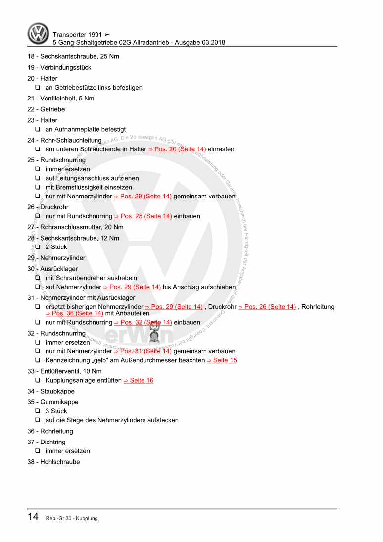
5 Gang-Schaltgetriebe 02G Allradantrieb

Beispielseite für Reparaturanleitung 5 Gang-Schaltgetriebe 02G Allradantrieb

Für Transporter Caravelle / Transporter Doppelkab / Transporter Kasten / Transporter Kombi/Cam / Transporter Pritsche (1991 - 1996)

23,09 € Details

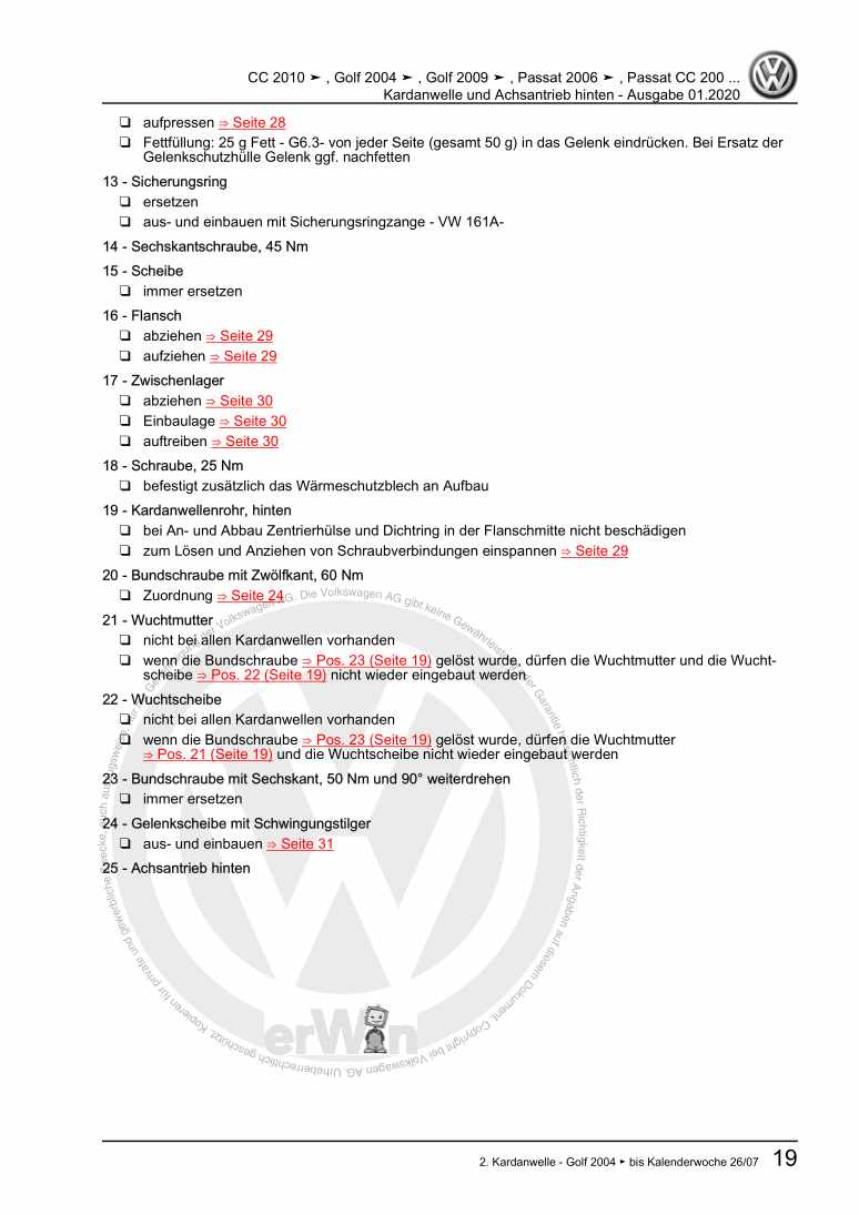
Kardanwelle und Achsantrieb hinten

Beispielseite für Reparaturanleitung Kardanwelle und Achsantrieb hinten

Für Passat / Passat Variant (2005 - 2008) / Golf (2004 - 2007) / Tiguan (2008) / Passat CC (2009) / Golf (2009) / Sharan (2011)

20,15 € Details

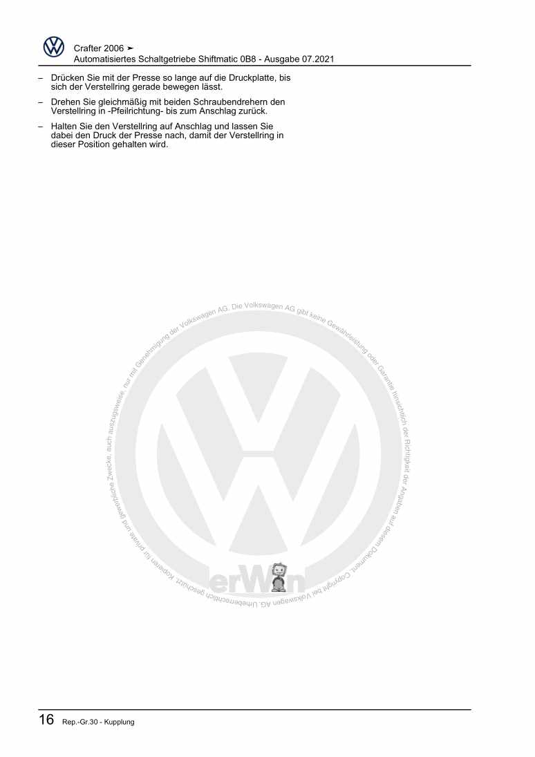
Automatisiertes Schaltgetriebe Shiftmatic 0B8

Beispielseite für Reparaturanleitung Automatisiertes Schaltgetriebe Shiftmatic 0B8

Für CRAFTER (2006 - 2007) / LT 2006> (2006 - 2007)

8,22 € Details

image/svg+xml Über Clonck

Originale Reparaturanleitungen und Ersatzteile

Unsere Reparaturanleitungen sind Originale, kommen direkt von Volkswagen und erfüllen die höchsten Qualitätsstandards.

In unserem Originalteile-Shop verkaufen wir hochwertige Originalersatzteile der Fahrzeughersteller. Mithilfe der Suche gibst du die gewünschte Teilenummer (OE-Nummer) ein und bestellst schnell und einfach das benötigte Ersatzteil.

Höchste Qualitätsstandards

Bei Clonck wollen wir Autoschrauber und Kfz-Profis glücklich machen. Aus diesem Grund findest du bei Clonck ausschließlich professionelle und hochwertige Reparaturanleitungen, mit deren Hilfe du dein Fahrzeug fachgerecht reparieren kannst.

Unsere Partner

Autohaus Schmidt GmbH
Automag GmbH Filiale Laim
KFZ-VERLAG GmbH
Zimpel und Franke GmbH

Clonck: Der Autoreparatur-Shop - gibt's auch als App!

Clonck App Logo Play Store

Clonck: Passende Autoteile für deine Autoreparatur

4,5 90

Mit Clonck bestellst du die richtigen Originalersatzteile im Handumdrehen.

  • Fahrzeugmodell hinzufügen
  • Baugruppe auswählen
  • Fahrzeug-Identifizierungsnummer (FIN) eingeben
  • Über 5.000 originale Reparaturanleitungen einsehen
Jetzt App starten
Clonck App Preview Auto Mobiltelefon Autoteile