Technical data
11 Checklist for evaluating running gear of accident vehicles
12 General information
3Front suspension
41 Appraisal of accident vehicles
42 Servicing front suspension
52.1 Overview - front axle
52.2 Raising wheel suspension to unladen position
63 Subframe, anti-roll bar, suspension links
83.1 Assembly overview: subframe, anti-roll bar, suspension links
83.2 Repairing thread in longitudinal member
113.3 Fixing position of subframe
113.4 Lowering subframe
133.5 Removing and installing subframe without steering rack
173.6 Removing and installing subframe with steering rack
213.7 Repairing subframe
263.8 Checking swivel joint
383.9 Removing and installing swivel joint
383.10 Removing and installing suspension link with mounting bracket
423.12 Renewing bonded rubber bush for suspension link
503.13 Renewing mounting bracket with suspension link bush
523.14 Removing and installing anti-roll bar
544 Assembly overview - wheel bearings
604.1 Removing and installing wheel bearing unit
624.2 Removing and installing wheel bearing housing
645 Assembly overview: suspension strut
695.1 Removing and installing suspension strut
705.2 Repairing suspension strut
766 Removing and installing drive shafts
796.1 Loosening and tightening twelve-point head bolt, with ribbing, securing drive shaft
796.3 Removing and installing drive shaft with constant velocity joint
826.5 Removing and installing right drive shaft with (push-on) constant velocity slip joint
906.7 Removing and installing drive shafts with triple roller joint AAR3300i (pushed into gearbox)
1027 Repairing drive shaft - overview of drive shafts
1077.1 Heat shields for drive shafts
1088 Assembly overview: drive shaft with VL107 constant velocity joint (bolt-on)
1098.1 Dismantling and assembling drive shaft with VL107 constant velocity joint
1118.2 Checking outer constant velocity joint
1158.3 Checking inner constant velocity joint
1169 Assembly overview: drive shaft with VL107 constant velocity slip joint
1189.2 Checking outer constant velocity joint
12410 Assembly overview: drive shaft with triple roller joint AAR3300i
12610.1 Dismantling and assembling drive shaft with triple roller joint AAR3300i
128Rear suspension
1401 Appraisal of accident vehicles
1402 Repairing rear suspension (front-wheel drive)
1412.1 Overview - rear axle
1412.2 Rear axle in unladen position
1433 Assembly overview: subframe up to model year 2010 (front-wheel drive)
1453.1 Removing and installing rear axle
1453.2 Repairing subframe
1494 Assembly overview: transverse link, track rod up to model year 2010 (front-wheel drive)
1544.1 Assembly overview: rear left vehicle level sender G76 , front-wheel drive
1574.2 Removing and installing rear left vehicle level sender G76
1574.3 Removing and installing upper transverse link
1584.4 Removing and installing lower transverse link
1604.5 Removing and installing track rod
1625 Allocation of track rods to trailing arms (front- and four-wheel drive)
1656.1 Assembly overview: rear left vehicle level sender G76 (front-wheel drive)
1696.2 Removing and installing rear left vehicle level sender G76
1696.3 Removing and installing rear axle
1706.4 Removing and installing upper transverse link
1736.5 Removing and installing lower transverse link
1756.6 Removing and installing track rod
1777 Assembly overview: wheel bearing housing, trailing arm (front-wheel drive)
1807.1 Removing and installing wheel bearing housing
1817.2 Renewing bonded rubber bush for wheel bearing housing
1857.3 Removing and installing wheel bearing/wheel hub unit
1877.4 Removing and installing trailing arm with mounting bracket
1907.5 Repairing trailing arm
1948 Assembly overview: shock absorber, coil spring (front-wheel drive)
1978.1 Removing and installing coil spring
1978.2 Removing and installing shock absorbers
1998.3 Repairing shock absorber
2019 Assembly overview: anti-roll bar (front-wheel drive)
2039.1 Removing and installing anti-roll bar
20310 Repairing rear suspension (four-wheel drive)
20610.1 Overview - rear axle
20610.2 Rear axle in unladen position
20811 Assembly overview: subframe, final drive (four-wheel drive)
21011.1 Removing and installing rear axle
21011.2 Repairing subframe, up to Week 21/2012
21511.3 Repairing subframe, as of Week 22/2012
22312 Assembly overview: transverse link, track rod (four-wheel drive)
23712.1 Overview - rear left vehicle level sender G76
24012.2 Removing and installing rear left vehicle level sender G76
24012.3 Removing and installing upper transverse link
24112.4 Removing and installing lower transverse link
24312.5 Removing and installing track rod
24513 Assembly overview: wheel bearing housing, trailing arm (four-wheel drive)
24913.1 Removing and installing wheel bearing housing
25113.2 Renewing bonded rubber bush for wheel bearing housing
25413.3 Removing and installing wheel bearing/wheel hub unit
25713.4 Removing and installing trailing arm with mounting bracket
25813.5 Repairing trailing arm
26114 Assembly overview: shock absorber, coil spring (four-wheel drive)
26414.1 Removing and installing coil spring
26414.2 Removing and installing shock absorbers
26614.3 Repairing shock absorber
26815 Assembly overview: anti-roll bar (four-wheel drive)
27015.1 Removing and installing anti-roll bar
27016 Assembly overview: drive shaft
27316.1 Loosening and tightening twelve-point head bolt, with ribbing, securing drive shaft
27416.3 Removing and installing drive shaft
27716.4 Dismantling and assembling drive shaft
28116.5 Checking inner constant velocity joint
285Self-levelling suspension
2871 Appraisal of accident vehicles
2872 Components of adaptive chassis control DCC and fitting locations
2882.1 Shock absorber damping adjustment button E387
2892.2 Removing and installing front left body acceleration sender G341
2892.3 Removing and installing front right body acceleration sender G342
2902.4 Renewing bracket for front left/right body acceleration sender G341/G342
2912.6 Removing and installing front left/right vehicle level sender G78/G289
2942.11 Removing and installing electronically controlled damping control unit J250
2992.12 Basic setting of adaptive chassis control DCC
2992.13 Cable routing left front axle
3002.14 Cable routing right front axle
3012.15 Cable routing rear axle
3023 Assembly overview: suspension strut for adaptive chassis control DCC
3033.1 Removing and installing suspension strut for adaptive chassis control DCC
3054 Assembly overview: shock absorber for adaptive chassis control DCC (front-wheel drive)
3134.1 Removing and installing rear body acceleration sender G343 (front-wheel drive)
3144.3 Repairing shock absorber for adaptive chassis control DCC (front-wheel drive)
3175 Assembly overview: shock absorber for adaptive chassis control DCC (four-wheel drive)
3205.1 Removing and installing rear body acceleration sender G343 (four-wheel drive)
321Wheels, tyres, vehicle geometry
3271 Appraisal of accident vehicles
3272 Torque settings for wheels
3283 Vehicle alignment check
3293.1 General information
3293.2 Conditions for testing
3313.3 Test preparations
3313.4 Wheel alignment specifications
3323.5 Overview - wheel alignment procedure
3333.6 Correcting front axle camber
3343.7 Adjusting camber on rear axle
3363.8 Adjusting toe at rear axle
3373.9 Adjusting front axle toe
3383.10 Basic setting of steering angle sensor G85
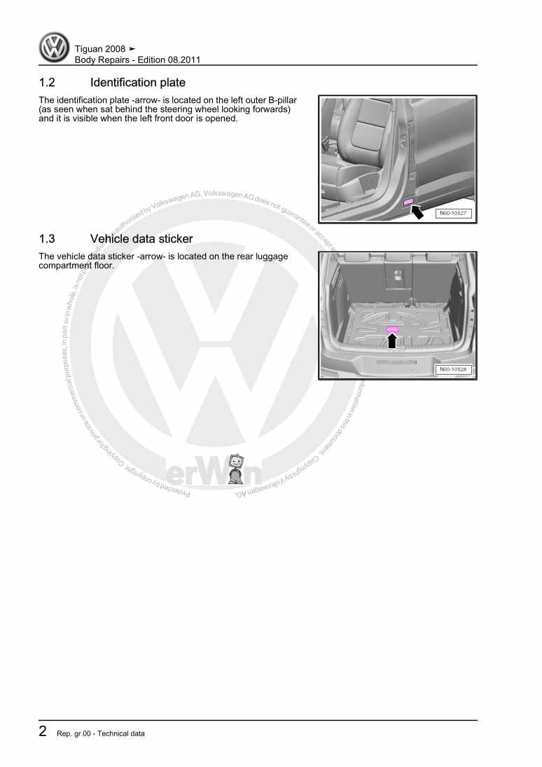
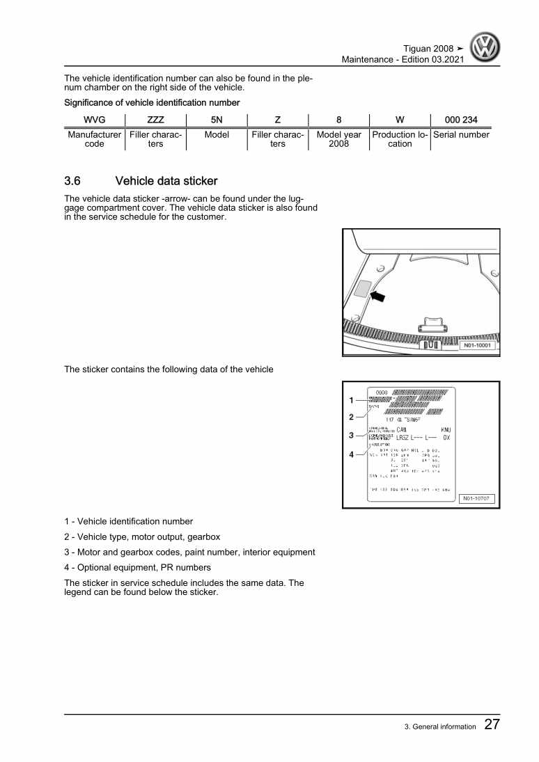
3393.11 Vehicle data sticker
3394 Front camera for driver assist systems R242
3404.1 Adjusting front camera for driver assistance system R242
340Steering
3481 Appraisal of accident vehicles
3482 General repair instructions
3492.1 Steering rack
3492.2 Gaskets and seals
3492.3 Nuts and bolts
3492.4 Electrical components
3502.5 Guided Fault Finding, vehicle self-diagnosis and Test Instruments
3503 Steering column and steering wheel
3513.1 Assembly overview: steering column, left-hand drive
3513.2 Assembly overview: steering column, right-hand drive
3523.3 Removing and installing steering wheel
3523.4 Removing and installing steering column
3553.6 Handling and transporting steering column
3603.7 Checking steering column for damage
3623.8 Removing and installing mounting bracket, RHD
3624 Electromechanical steering rack
3644.1 Assembly overview - electromechanical steering rack, left-hand drive
3644.4 Removing and installing steering rack, left-hand drive vehicle
3694.5 Removing and installing steering rack, right-hand drive vehicle
3785 Differentiating between 2nd and 3rd generation steering racks
3886 Repairing electromechanical steering rack, left-hand drive vehicles
3896.1 Assembly overview: electromechanical steering rack, LHD vehicle
3896.2 Renewing bonded rubber bushes for power-assisted steering rack
3906.3 Removing and installing boot
3926.4 Checking play, security and boots of track rod ends
3946.5 Removing and installing track rod
3947 Repairing electromechanical steering rack, right-hand drive vehicles
3987.1 Assembly overview: electromechanical steering rack, RHD vehicle
3987.2 Removing and installing boot
3997.3 Checking play, security and boots of track rod ends
4017.4 Removing and installing track rod
401
