Technical data
11 Technical data
11.1 Engine number
11.2 Engine data
1Removing and installing engine
31 Engine and gearbox
31.1 Removing and installing engine cover
31.2 Removing motor
31.3 Separating engine and gearbox
201.4 Removing and installing engine supports
271.5 Securing engine on engine and gearbox support
311.6 Installing engine
351.7 Supporting engine in installation position
401.8 Removing and installing engine mounting
422 Assembly mountings
442.1 Assembly overview - assembly mountings
442.2 Removing and installing left engine mounting
452.3 Removing and installing right engine mounting
47Crankshaft group
491 Cylinder block (pulley end)
491.1 Assembly overview - poly V-belt drive
491.2 Removing and installing poly-V belt
511.3 Removing and installing tensioning element for poly V-belt
531.4 Removing and installing vibration damper
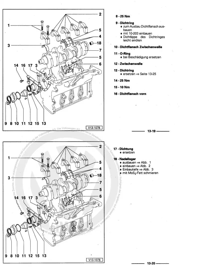
531.5 Assembly overview - oil seal and sealing flange on pulley end
551.6 Replacing oil seal for crankshaft at belt pulley end
561.7 Removing and installing sealing flange on pulley end
582 Cylinder block, gearbox end
642.1 Assembly overview - drive plate
642.2 Removing and installing drive plate
642.3 Renewing oil seal for crankshaft at gearbox end
652.4 Removing and installing engine speed sender G28
683 Crankshaft
693.1 Assembly overview - crankshaft
693.2 Allocation of main bearing shells for new crankshaft
713.4 Crankshaft dimensions
753.5 Measuring axial clearance
753.6 Measuring radial clearance
764 Pistons and conrods
774.1 Assembly overview - pistons and conrods
774.2 Measuring piston projection at “TDC”
824.3 Piston and cylinder dimensions
854.4 Measuring radial clearance of conrods
854.5 Allocation of conrod bearing shells
85Cylinder head, valve gear
861 Timing chain covers
861.1 Assembly overview - timing chain covers
861.2 Renewing oil seal for toothed belt pulley
891.3 Removing and installing timing chain cover (left)
911.4 Removing and installing timing chain cover (right)
941.5 Removing and installing timing chain cover (bottom)
972 Chain drive
1032.1 Assembly overview - camshaft timing chains
1032.2 Removing camshaft timing chains from camshafts
1052.3 Removing and installing camshaft timing chains
1172.4 Assembly overview - drive chain for valve gear
1292.5 Removing and installing drive chain for valve gear
1312.6 Assembly overview - drive chain for auxiliary drives
1322.7 Removing and installing drive chain for auxiliary drives
1322.8 Assembly overview - auxiliary drives
1342.9 Renewing oil seal for vane pump drive
1362.10 Removing and installing spur gear drive
1373 Cylinder head
1423.1 Assembly overview - cylinder head cover
1423.2 Removing and installing cylinder head cover
1443.3 Assembly overview - cylinder head
1463.4 Removing cylinder head
1493.5 Installing cylinder head
1523.6 Checking compression
1574 Valve gear
1594.1 Assembly overview - valve gear
1594.2 Measuring axial clearance of camshaft
1614.3 Measuring radial clearance of camshafts
1624.4 Removing and installing camshafts
1634.5 Checking hydraulic compensation elements
1704.6 Renewing valve stem seals with cylinder head installed
1724.7 Renewing valve stem seals with cylinder head removed
1774.8 Valve dimensions
1824.9 Reworking valve seats
1824.10 Checking valve guides
1824.11 Checking valves
184Lubrication
1851 Engine oil:
1851.1 Oil capacities
1851.2 Using tester to check engine oil level
1852 Oil pump, lower part of sump, upper part of sump
1872.1 Assembly overview - oil pump, lower part of sump, upper part of sump
1872.2 Removing and installing oil level and oil temperature sender G266
1912.3 Removing and installing lower part of sump
1912.4 Removing and installing oil pump
1952.5 Removing and installing upper part of sump
1963.2 Removing and installing engine oil cooler
2033.3 Removing and installing oil filter housing
2053.4 Removing and installing pressure control valve for crankcase breather system
2073.6 Removing and installing oil pressure switch F22
2093.7 Removing and installing oil pressure switch for reduced oil pressure F378
2093.8 Removing and installingoil temperature sender G8
2103.9 Removing and installing oil pressure regulating valve N428
2103.10 Checking oil pressure
212Cooling
2141 Cooling system
2141.1 Coolant hose connection diagram
2141.2 Locations
2151.3 Assembly overviews
2181.4 Assembly overview - pump for exhaust gas recirculation cooler V400
2211.5 Removing and installing pump for exhaust gas recirculation cooler V400
2222 Coolant
2242.1 Draining coolant
2242.2 Draining cooling system
2252.3 Filling with coolant
2272.4 Checking filling quality
2302.5 Checking cooling system for leaks
2313 Radiator module and radiator fan
2343.1 Assembly overview - radiator module and radiator fan
2343.2 Removing and installing radiator cowl and radiator fan
2343.3 Removing, installing and dismantling radiator module
2364 Coolant pump and thermostat
2424.1 Assembly overview - coolant pump and thermostat
2424.2 Removing and installing coolant pump
2434.3 Removing and installing thermostat
247Turbocharging/supercharging
2501 Rules for cleanliness
2502 Turbocharger
2512.1 Assembly overview - turbocharger
2512.2 Removing and installing turbocharger on left
2542.3 Removing and installing turbocharger on right
2582.4 Removing and installing sender 1 for turbocharger speed G688
2612.5 Removing and installing sender 2 for turbocharger speed G689
2633 Charge air cooling
2663.1 Assembly overview - air ducts
2663.2 Assembly overview - charge air cooling
2673.3 Removing and installing charge air cooler
2683.5 Checking charge air system for leaks
2714 Vacuum system
2744.1 Overview - vacuum system
2744.2 Checking vacuum system
274Mixture preparation - injection
2761 Safety precautions and rules for cleanliness
2761.1 Safety precautions
2761.2 Rules for cleanliness and instructions for working on fuel system
2772 Diesel direct injection system
2802.1 Schematic overview of the fuel system
2812.2 Assembly overview - fuel system
2832.3 Assembly overview - injectors and high-pressure lines
2872.4 Removing and installing injectors
2912.5 Testing injectors
2962.6 Checking and setting injector correction values
2962.7 Measuring return rate of injectors with engine running
2972.8 Measuring return rate of injection units at starter speed
3012.9 Testing jammed-open injectors
3032.10 Checking throttle in fuel return line
3052.11 Installing high-pressure lines
3062.12 Installing fuel return lines
3082.13 Assembly overview - toothed belt for high-pressure pump
3082.14 Removing and installing toothed belt for high-pressure pump
3092.15 Assembly overview - high-pressure pump
3172.16 Removing and installing high-pressure pump
3192.17 Checking fuel pressure regulating valve N276
3212.18 Removing and installing fuel pressure regulating valve N276
3222.19 Removing and installing fuel pressure sender G247
3242.20 Bleeding fuel system/filling tank with fuel for first time
3252.21 Checking fuel system for leaks
3263 Intake manifolds
3273.1 Assembly overview - intake manifolds
3273.2 Removing and installing intake manifold upper part
3293.3 Removing and installing lower part of intake manifold on right (cylinder bank 1)
3303.4 Removing and installing lower part of intake manifold on left (cylinder bank 2)
3314 Air filter
3334.1 Assembly overview - air filter
3334.2 Removing and installing lower part of air filter
3355 Engine control units
3375.1 Removing and installing engine control unit J623 and engine control unit 2 J624
337Exhaust system
3401 Particulate filters and catalytic converters
3401.1 Assembly overview - particulate filters and catalytic converters
3401.2 Removing and installing particulate filter
3421.3 Removing and installing catalytic converters
3452 Silencers and exhaust manifolds
3482.1 Silencer
3482.2 Exhaust manifold
3543 Lambda probes, exhaust temperature and pressure senders
3593.1 Assembly overview - Lambda probes, exhaust temperature and pressure senders
3593.2 Removing and installing exhaust gas temperature sender 1 G235
3613.4 Removing and installing Lambda probe G39 with Lambda probe heater Z19
3633.5 Removing and installing Lambda probe 2 G108
3654 Exhaust gas recirculation
3754.1 Assembly overview - exhaust gas recirculation
3754.2 Removing and installing exhaust gas recirculation control motor V338/V339
3774.3 Assembly overview - exhaust gas recirculation cooler
3784.4 Removing and installing exhaust gas recirculation cooler
3804.5 Removing and installing exhaust gas recirculation temperature sensor G98
382Glow plug system
3831 Removing and installing glow plugs
383