Technical data
11 Identification
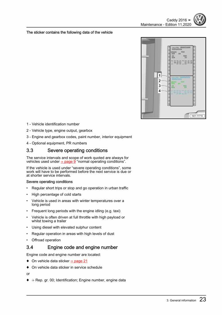
11.1 Engine number/engine data
12 Safety information
22.1 Safety regulations for working on fuel supply
22.2 Safety precautions when working on fuel system
22.3 Safety precautions when working on the cooling system
33 Repair instructions
53.1 Rules for cleanliness
53.2 General repair instructions
6Removing and installing engine
81 Removing and installing engine
81.1 Removing engine
81.2 Separating engine and gearbox
231.3 Securing engine on engine and gearbox support
281.4 Installing engine
292 Assembly mountings
342.1 Assembly overview - assembly mountings
342.2 Removing and installing engine mounting
382.3 Supporting engine in installation position
412.4 Adjusting assembly mountings
433 Engine cover panel
493.1 Removing and installing engine cover
49Crankshaft group
511 Cylinder block (pulley end)
511.1 Assembly overview - poly V-belt drive
511.2 Assembly overview - cylinder block (pulley end)
531.3 Assembly overview - sealing flange, belt pulley end
561.4 Removing and installing poly-V belt
571.5 Removing and installing tensioner for poly V-belt
601.6 Removing and installing bracket for ancillaries
621.7 Removing and installing vibration damper
651.8 Removing and installing engine bracket
661.9 Renewing crankshaft oil seal - belt pulley end
701.10 Removing and installing sealing flange on pulley end
722 Cylinder block, gearbox end
782.1 Assembly overview - cylinder block, gearbox end
782.2 Removing and installing flywheel
792.3 Removing and installing sealing flange on gearbox side
803 Crankshaft
913.1 Assembly overview - crankshaft
913.2 Crankshaft dimensions
923.3 Measuring axial clearance of crankshaft
933.4 Measuring radial clearance of crankshaft
943.5 Renewing needle bearing in crankshaft
944 Pistons and conrods
974.1 Assembly overview - pistons and conrods
974.2 Measuring piston projection at TDC
1004.3 Checking pistons and cylinder bores
1014.4 Separating new conrod
1044.5 Checking radial clearance of conrods
1044.6 Removing and installing oil spray jets
105Cylinder head, valve gear
1071 Cylinder head
1071.1 Assembly overview - cylinder head
1071.2 Assembly overview - cylinder head cover
1111.3 Removing and installing cylinder head
1131.4 Removing and installing cylinder head cover
1301.5 Removing and installing injector seals
1331.6 Removing and installing vacuum pump
1361.7 Checking compression
1372 Fully enclosing toothed belt guard
1402.1 Assembly overview - fully enclosing toothed belt guard
1402.2 Removing and installing upper toothed belt guard (fully enclosing)
1422.3 Removing and installing lower toothed belt guard (fully enclosed)
1432.4 Removing and installing rear toothed belt guard (fully enclosing)
1443 Toothed belt drive
1493.1 Assembly overview - toothed belt
1493.2 Removing and installing toothed belt
1524 Valve gear
1704.1 Assembly overview - valve gear
1704.2 Measuring axial play of camshaft
1734.3 Measuring radial play of camshaft
1754.4 Removing and installing camshaft
1754.5 Removing and installing camshaft oil seal
1854.6 Checking hydraulic compensation elements
1914.7 Removing and installing valve stem seals
1925 Inlet and exhaust valves
2015.1 Reworking valve seats
2015.2 Checking valve guides
2015.3 Checking valves
2025.4 Valve dimensions
203Lubrication
2041 Sump, oil pump
2041.1 Assembly overview - sump/oil pump
2041.2 Engine oil:
2071.3 Removing and installing oil sump
2081.4 Removing and installing oil pump
2131.5 Removing and installing oil level and oil temperature sender G266
2142 Engine oil cooler
2162.1 Removing and installing engine oil cooler
2162.2 Checking engine oil cooler for leaks
2203 Oil filter, oil pressure switch
2233.1 Assembly overview - oil filter housing, oil pressure switch
2233.2 Removing and installing oil pressure switch F1
2253.3 Checking oil pressure and oil pressure switch
2263.4 Removing and installing oil filter housing
2284 Oil circuit
2334.1 Assembly overview - oil circuit
2334.2 Removing and installing oil supply line
233Cooling
2401 Cooling system/coolant
2401.1 Connection diagram - coolant hoses
2401.2 Checking cooling system for leaks
2411.3 Draining and adding coolant
2442 Coolant pump, regulation of cooling system
2542.1 Assembly overview - coolant pump, thermostat
2542.2 Removing and installing coolant circulation pump 2 V178
2542.3 Removing and installing coolant pump
2572.4 Removing and installing 4/2-way valve with thermostat
2582.5 Removing and installing coolant temperature sender G62
2612.6 Removing and installing radiator outlet coolant temperature sender G83
2623 Coolant pipes
2653.1 Assembly overview - coolant pipes
2653.2 Removing and installing coolant pipes
2673.3 Removing and installing upper coolant pipes
2774 Radiator, radiator fan
2794.1 Assembly overview - radiator/radiator fan
2794.2 Removing and installing radiator
2814.3 Removing and installing radiator cowl with radiator fan
2824.4 Removing and installing radiator fan VX57
2834.5 Removing and installing radiator fan 2 V177
284Turbocharging/supercharging
2861 Turbocharger
2861.1 Assembly overview - turbocharger
2861.2 Removing and installing turbocharger
2901.3 Renewing vacuum unit for turbocharger
2972 Charge air system
3062.1 Assembly overview - charge air system
3062.2 Assembly overview - charge-air hose connections
3082.3 Removing and installing charge air cooler
3102.4 Removing and installing air pipe
3122.6 Checking charge air system for leaks
315Mixture preparation - injection
3191 Injection system
3191.1 Schematic overview - fuel system
3191.2 Overview of fitting locations - injection system
3211.3 Filling/bleeding fuel system
3311.4 Checking fuel system for leaks
3322 Vacuum system
3342.1 Connection diagram – vacuum system
3342.2 Checking vacuum system
3352.3 Removing and installing charge pressure control solenoid valve N75
3443 Injectors/high-pressure accumulator (rail)
3473.1 Assembly overview - injectors
3473.2 Adapting correction values for injectors
3503.3 Testing injectors
3513.4 Checking return flow rate of injectors with engine running
3513.5 Checking return flow rate of injectors at starter speed
3543.6 Testing jammed-open injectors
3563.7 Removing and installing injectors
3583.8 Removing and installing high-pressure lines
3633.9 Removing and installing fuel rail
3694 Air filter
3754.1 Assembly overview - air filter housing
3754.2 Removing and installing air filter housing
3775 Intake manifold
3805.1 Assembly overview – intake manifold
3805.2 Removing and installing intake manifold
3825.3 Removing and installing throttle valve module GX3
3866 Senders and sensors
3896.1 Removing and installing exhaust gas pressure sensor 1 G450
3896.2 Removing and installing air mass meter G70
3906.3 Checking fuel pressure regulating valve N276
3916.4 Removing and installing fuel pressure regulating valve N276
3926.5 Removing and installing fuel pressure sender G247
3967 Engine control unit
3997.1 Removing and installing engine control unit J623
3997.2 Removing and installing engine (motor) control unit J623 with protective housing
4018 High-pressure pump
4058.1 Assembly overview - high-pressure pump
4058.2 Removing and installing high-pressure pump
4078.3 Checking high-pressure pump
4119 Lambda probe
4149.1 Removing and installing Lambda probe
414Exhaust system
4161 Exhaust pipes and silencers
4161.1 Assembly overview – silencers
4161.2 Separating exhaust pipes from silencers
4171.3 Aligning exhaust system free of stress
4191.4 Installation position of clamp
4202 Emission control
4222.1 Assembly overview – emission control
4222.2 Removing and installing particulate filter
4253 Exhaust gas temperature regulation
4363.1 Assembly overview – exhaust gas temperature regulation
4363.2 Removing and installing exhaust gas temperature sender 1 G235
4373.3 Removing and installing exhaust gas temperature sender 3 G495
4383.4 Removing and installing exhaust gas temperature sender 4 G648
4404 Exhaust gas recirculation
4434.1 Assembly overview – exhaust gas recirculation
4434.2 Removing and installing exhaust gas recirculation cooler
4454.3 Checking changeover for exhaust gas recirculation cooler
4484.4 Checking exhaust gas recirculation cooler for leaks
4494.5 Cleaning exhaust gas recirculation system
449Glow plug system
4591 Glow plug system
4591.1 Removing and installing glow plug
4591.2 Removing and installing automatic glow period control unit J179
4611.3 Removing and installing engine speed sender G28
4611.4 Removing and installing Hall sender G40
462
