Technical data
11 Safety information
11.1 Safety regulations for working on fuel supply
11.2 Safety measures when working on vehicles with a start/stop system
21.4 Safety precautions when working on the cooling system
21.5 Safety precautions when working on the SCR system
21.6 Safety precautions when working on exhaust system
32 Identification
52.1 Engine number/engine data
53 Repair instructions
73.1 Rules for cleanliness
73.2 Foreign objects in engine
73.3 Contact corrosion
73.4 Routing and attachment of lines
83.5 Fitting radiator and condensers
8Removing and installing engine
91 Removing and installing engine
91.1 Removing engine
91.2 Separating engine and gearbox
221.3 Securing engine on engine and gearbox support
271.4 Installing engine
292 Assembly mountings
342.1 Assembly overview – assembly mountings
342.2 Removing and installing engine mounting
362.3 Removing and installing gearbox mounting
372.4 Removing and installing pendulum support
392.5 Supporting engine in installation position
412.6 Adjusting assembly mountings
512.7 Checking adjustment of assembly mountings
533 Engine cover panel
553.1 Removing and installing engine cover
55Crankshaft group
561 Cylinder block (pulley end)
561.1 Assembly overview - cylinder block (pulley end)
561.2 Assembly overview - sealing flange, belt pulley end
591.3 Removing and installing poly-V belt
601.4 Removing and installing tensioner for poly V-belt
611.5 Removing and installing vibration damper
621.6 Removing and installing bracket for ancillaries
631.7 Removing and installing engine support
651.8 Removing and installing sealing flange on pulley end
662 Cylinder block, gearbox end
712.1 Assembly overview - cylinder block, gearbox end
712.2 Removing and installing flywheel
742.3 Removing and installing sealing flange on gearbox side
753 Crankshaft
993.1 Assembly overview - crankshaft
993.2 Crankshaft dimensions
1013.3 Measuring axial clearance of crankshaft
1013.4 Renewing needle bearing in crankshaft
1024 Pistons and conrods
1064.1 Assembly overview - pistons and conrods
1064.2 Removing and installing pistons
1114.3 Measuring piston projection at TDC
1134.4 Checking pistons and cylinder bores
1154.5 Checking radial clearance of conrods
118Cylinder head, valve gear
1191 Cylinder head
1191.1 Assembly overview - cylinder head
1191.2 Assembly overview - cylinder head cover
1231.3 Removing and installing cylinder head
1251.4 Removing and installing cylinder head cover
1371.5 Removing and installing injector seals
1381.6 Removing and installing camshaft housing
1391.7 Checking compression
1472 Toothed belt drive
1502.1 Assembly overview - toothed belt cover
1502.2 Assembly overview - toothed belt
1512.3 Removing and installing toothed belt guard
1532.4 Removing and installing toothed belt
1572.5 Removing toothed belt from camshaft
1703 Valve gear
1803.1 Assembly overview - valve gear
1803.2 Measuring axial play of camshaft
1823.3 Removing and installing camshaft oil seal
1833.4 Checking hydraulic compensation elements
1853.5 Removing and installing valve stem seals
1864 Inlet and exhaust valves
2034.1 Checking valve guides
2034.2 Checking valves
2044.3 Valve dimensions
204Lubrication
2061 Sump, oil pump
2061.1 Assembly overview - sump/oil pump
2061.2 Engine oil:
2101.3 Removing and installing lower part of sump
2101.4 Removing and installing upper part of sump
2151.5 Removing and installing oil pump
2191.6 Removing and installing oil level and oil temperature sender G266
2192 Engine oil cooler
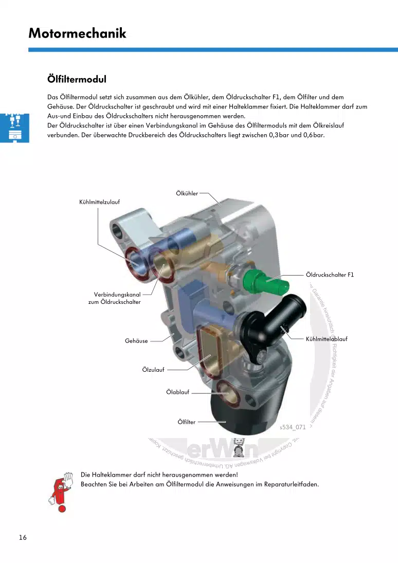
2213 Oil filter, oil pressure switch
2223.1 Assembly overview - oil filter housing, oil pressure switch
2223.2 Assembly overview - oil pressure switches/oil pressure control
2243.3 Removing and installing oil pressure sender G10
2253.4 Checking oil pressure
2263.5 Removing and installing oil filter housing
2273.6 Removing and installing oil pressure regulating valve N428
2293.7 Removing and installing piston cooling jet control valve N522
2304 Oil circuit
2314.1 Removing and installing oil supply line
2314.2 Removing and installing oil return line for turbocharger
232Cooling
2341 Cooling system/coolant
2341.1 Connection diagram - coolant hoses
2341.2 Checking cooling system for leaks
2361.3 Draining coolant
2391.4 Filling with coolant
2411.5 Checking filling quality of cooling system
2601.6 Checking electric vacuum pump VAS 6096/2
2621.7 Flushing cooling system
2632 Coolant pump, regulation of cooling system
2852.1 Assembly overview - coolant pump, thermostat
2852.2 Assembly overview - electric coolant pump
2882.3 Assembly overview - coolant temperature sender
2902.4 Removing and installing electric coolant pump
2922.5 Removing and installing coolant pump
3002.6 Removing and installing coolant distribution module
3022.7 Removing and installing coolant regulating valve N515
3042.8 Removing and installing coolant temperature sender G62
3062.9 Removing and installing engine outlet coolant temperature sender G82
3082.10 Removing and installing coolant temperature sender for charge air cooler G1130
3103 Coolant pipes
3133.1 Assembly overview - coolant pipes
3133.2 Removing and installing coolant pipes
3144 Radiator, radiator fan
3224.1 Assembly overview - radiator/radiator fan
3224.2 Assembly overview – radiator cowl and radiator fan
3254.3 Removing and installing radiator
3264.4 Removing and installing water radiator for charge air cooling circuit
3284.5 Removing and installing radiator cowl
3344.6 Removing and installing radiator fan
335Turbocharging/supercharging
3371 Turbocharger
3371.1 Assembly overview - turbocharger
3371.2 Removing and installing turbocharger
3401.3 Removing and installing connection for turbocharger
3452 Charge air system
3472.1 Assembly overview - charge air system
3472.2 Removing and installing charge pressure sender GX26
3472.3 Checking charge air system for leaks
3472.4 Removing and installing air pipe
3502.5 Checking charge air cooler for leaks
351Mixture preparation - injection
3571 Injection system
3571.1 Schematic overview - fuel system
3571.2 Overview of fitting locations - injection system
3591.3 Filling/bleeding fuel system
3711.4 Checking fuel system for leaks
3712 Injectors/high-pressure accumulator (rail)
3732.1 Assembly overview - injectors
3732.2 Assembly overview - fuel rail
3752.3 Adapting correction values for injectors
3762.4 Testing injectors
3772.5 Checking return flow rate of injectors with engine running
3782.6 Checking return flow rate of injectors at starter speed
3812.7 Testing jammed-open injectors
3832.8 Removing and installing injectors
3852.9 Removing and installing high-pressure lines
3892.10 Removing and installing fuel rail
3943 Air filter
3993.1 Assembly overview - air filter housing
3993.2 Removing and installing air filter housing
4013.3 Removing and installing air guide on lock carrier
4034 Intake manifold
4054.1 Assembly overview – intake manifold
4054.2 Removing and installing intake manifold
4104.3 Removing and installing throttle valve module GX3
4175 Senders and sensors
4205.1 Removing and installing fuel pressure regulating valve N276
4205.2 Checking fuel pressure regulating valve N276
4225.3 Removing and installing fuel pressure sender G247
4235.4 Removing and installing air mass measurement module GX35
4255.5 Removing and installing pressure differential sender G505
4275.6 Removing and installing NOx sender 2 G687
4295.7 Removing and installing NOx sender 3 G932
4305.10 Removing and installing NOx sender G295
4335.11 Removing and installing particle sensor G784
4356 Engine control unit
4396.1 Removing and installing engine control unit J623
4396.2 Removing and installing engine control unit J623 (with protective housing)
4407 High-pressure pump
4477.1 Assembly overview - high-pressure pump
4477.2 Removing and installing high-pressure pump
4478 Lambda probe
4528.1 Assembly overview - Lambda probe
4528.2 Removing and installing Lambda probe
453Exhaust system
4551 Exhaust pipes and silencers
4551.1 Assembly overview – silencers
4551.2 Assembly overview - front exhaust pipe
4561.3 Separating exhaust pipes from silencers
4601.4 Removing and installing silencer
4611.5 Aligning exhaust system free of stress
4621.6 Checking exhaust system for leaks
4621.7 Installation position of clamp
4631.8 Align end exhaust pipes
4642 Emission control
4652.1 Assembly overview – emission control
4652.2 Removing and installing emission control module
4672.3 Removing and installing exhaust flap control unit J883
4752.4 Removing and installing ammonia traps
4773 SCR system (selective catalytic reduction)
4803.1 Overview of fitting locations – SCR system (selective catalytic reduction)
4803.2 Assembly overview - tank for reducing agent
4863.3 Assembly overview – filler tube for reducing agent tank
4943.4 Assembly overview - reducing agent supply line
4983.5 Assembly overview - delivery unit for reducing agent metering system GX19
5083.6 Removing and installing reducing agent tank
5093.7 Removing and installing front section of reducing agent supply line
5223.9 Removing and installing injector for reduction agent N474
5283.10 Removing and installing injector 2 for reducing agent N758
5313.11 Removing and installing control unit for reducing-agent heater J891
5333.12 Assembly overview - injector for reducing agent N474
5443.13 Assembly overview – injector 2 for reducing agent N758
5453.14 Draining reducing agent tank
5463.15 Removing and installing middle section of reducing agent supply line
5503.16 Removing and installing rear section of reducing agent supply line
5513.17 Removing and installing filler pipe for reducing agent tank
5593.18 Disconnecting reducing agent supply line
5683.19 SCR - resetting learnt values
5734 Exhaust gas temperature regulation
5754.1 Assembly overview – exhaust gas temperature regulation
5754.2 Removing and installing exhaust gas temperature sender 1 G235
5764.3 Removing and installing exhaust gas temperature sender 2 G448
5784.4 Removing and installing exhaust gas temperature sender 3 G495
5804.5 Removing and installing exhaust gas temperature sender 4 G648
5825 Exhaust gas recirculation
5865.1 Assembly overview – exhaust gas recirculation
5865.2 Removing and installing exhaust gas recirculation cooler
5895.3 Removing and installing exhaust gas recirculation valve 1 GX5
5925.4 Removing and installing exhaust gas recirculation valve 2 GX6
5935.5 Removing and installing exhaust gas recirculation temperature sensor G98
5945.6 Checking exhaust gas recirculation cooler for leaks
595Glow plug system
6011 Glow plug system
6011.1 Assembly overview - glow plug system
6011.2 Removing and installing glow plug
6031.3 Removing and installing automatic glow period control unit J179
6071.4 Removing and installing Hall sender G40
6081.5 Removing and installing engine speed sender G28
608