DER AUTOREPARATUR-SHOP
0
Home » Anleitungen » Running gear, axles, steering
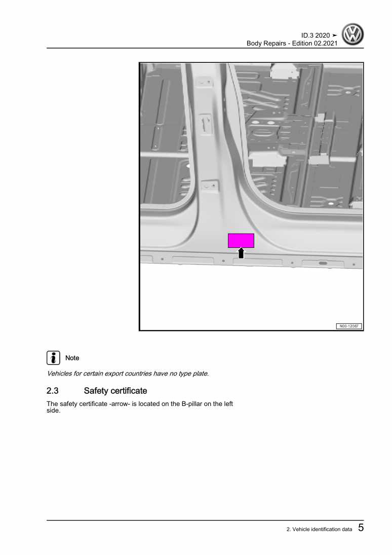
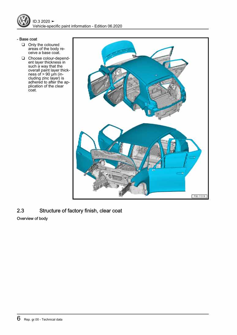
  • Beispielseite für Reparaturanleitung Running gear, axles, steering
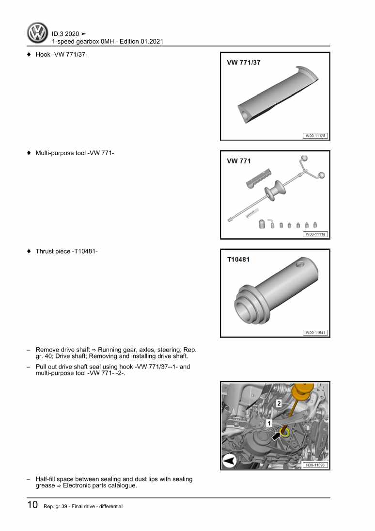
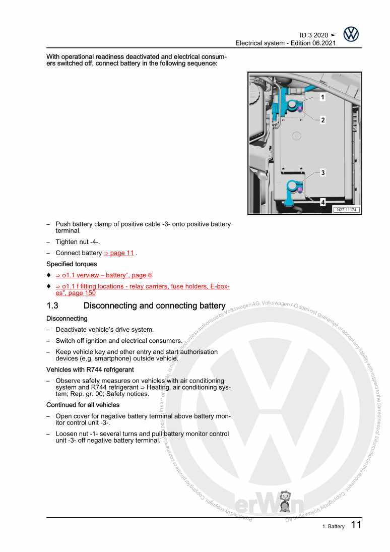
  • Beispielseite für Reparaturanleitung 2 Running gear, axles, steering
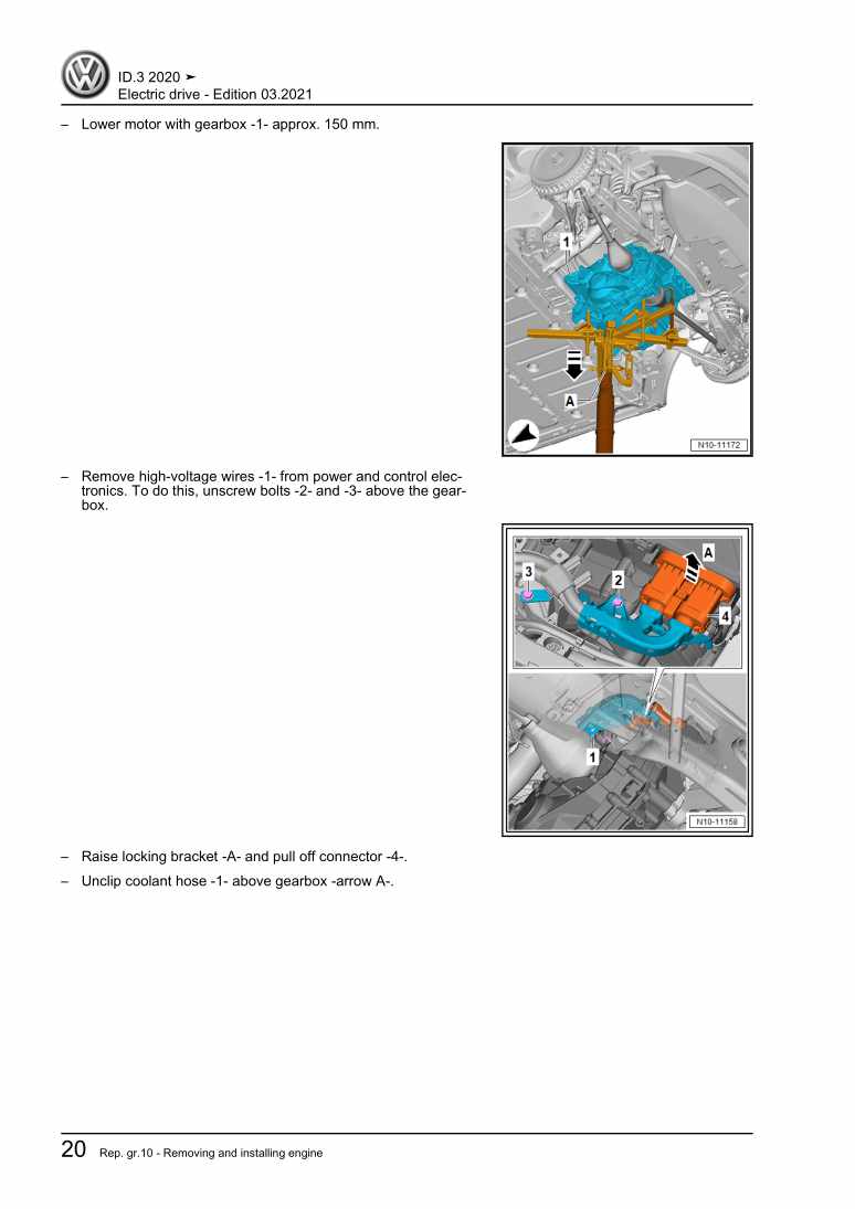
  • Beispielseite für Reparaturanleitung 3 Running gear, axles, steering
  • Beispielseite für Reparaturanleitung Running gear, axles, steering
  • Beispielseite für Reparaturanleitung 2 Running gear, axles, steering
  • Beispielseite für Reparaturanleitung 3 Running gear, axles, steering

Running gear, axles, steering

Für ID.3

Original VW-Reparaturanleitung


19,30 €inkl. 7% MwSt.

Sofort als Download verfügbar

Sprache: English

Digitale PDF Version

22.008 KB

237 Seiten

Detaillierte technische Daten

Sofort lesbar

Diese Reparaturanleitung umfasst: Front axle, Subframe, Suspension strut, upper suspension link, Wheel bearing, Drive shaft, Electronically controlled damping system und Vehicle level sender. Mehr anzeigen
Sichere Zahlung per PayPal, Kreditkarte, Lastschrift, Sofort-Überweisung oder Giropay
PayPal Logo SEPA Lastschrift Logo Giropay Logo Sofort Überweisung Logo

Reparaturanleitung ID.3 Running gear, axles, steering pdf Download mit dem Inhalt:

Kapitelübersicht

  • Technical data
    1
  • 1 Safety information
    1
  • 1.2 Safety precautions when working on subframe
    1
  • 1.3 Safety precautions when working on the cooling system
    1
  • 1.4 Safety precautions when working on a high-voltage system
    2
  • 1.5 Safety precautions when working in the vicinity of high-voltage components
    2
  • 2 Repair instructions
    4
  • 2.1 Leaks at shock absorbers
    4
  • 2.2 Noises from shock absorbers
    4
  • 2.3 Checking shock absorbers when removed
    5
  • 2.4 Steering rack
    5
  • 2.5 Gaskets and seals
    6
  • 2.6 Nuts and bolts
    6
  • 2.7 Electrical components
    6
  • 3 Evaluating accident vehicles
    7
  • 3.1 Check list for evaluating running gear on accident vehicles
    7
  • 4 Disposal
    9
  • 4.1 Releasing gas and draining front gas-filled shock absorbers
    9
  • 4.2 Releasing gas and draining rear gas-filled shock absorbers
    11
  • Front suspension
    12
  • 1 Front axle
    12
  • 1.1 Overview of fitting locations – front axle
    12
  • 2 Subframe
    13
  • 2.1 Assembly overview – subframe
    13
  • 2.2 Assembly overview – anti-roll bar
    14
  • 2.3 Removing and installing subframe without steering rack
    14
  • 2.4 Removing and installing subframe with steering rack
    17
  • 2.5 Removing and installing anti-roll bar
    19
  • 2.6 Removing and installing coupling rod
    21
  • 2.7 Repairing thread in longitudinal member
    22
  • 2.8 Fixing subframe in position
    22
  • 2.9 Taking up weight of front axle with scissor-type assembly platform
    24
  • 3 Suspension strut, upper suspension link
    27
  • 3.1 Assembly overview - suspension strut, upper suspension link
    27
  • 3.2 Removing and installing suspension strut
    29
  • 3.3 Repairing suspension strut
    32
  • 4 Lower suspension link, swivel joint
    38
  • 4.1 Assembly overview - lower suspension link, swivel joint
    38
  • 4.2 Removing and installing lower suspension link
    40
  • 4.3 Checking swivel joint
    41
  • 4.4 Removing and installing swivel joint
    42
  • 4.5 Renewing bonded rubber bush for lower suspension link
    44
  • 4.6 Removing and installing shield for suspension link
    53
  • 5 Wheel bearing
    54
  • 5.1 Assembly overview – wheel bearing assembly
    54
  • 5.2 Removing and installing wheel bearing housing
    57
  • 5.3 Removing and installing wheel bearing unit
    60
  • 5.4 Loosening and tightening wheel bearing threaded connection on outside
    62
  • Rear suspension
    64
  • 1 Rear axle
    64
  • 1.1 Overview – rear axle
    64
  • 1.2 Removing and installing rear axle
    66
  • 1.3 Taking up weight of rear axle with scissor-type assembly platform
    71
  • 1.4 Lowering rear axle
    76
  • 1.5 Securing vehicle to support arms of lifting platform
    79
  • 2 Subframe
    82
  • 2.1 Assembly overview – subframe
    82
  • 2.2 Fixing subframe in position
    84
  • 2.3 Renewing subframe mountings
    86
  • 2.4 Renewing motor mountings
    106
  • 2.5 Renewing gearbox mounting
    116
  • 3 Anti-roll bar
    126
  • 3.1 Assembly overview – anti-roll bar
    126
  • 3.2 Removing and installing anti-roll bar
    128
  • 3.3 Removing and installing coupling rod
    128
  • 4 Suspension link, track rod
    130
  • 4.1 Assembly overview - transverse link
    130
  • 4.2 Assembly overview - transverse link
    132
  • 4.3 Assembly overview – spring control arm
    134
  • 4.4 Assembly overview – track rod
    136
  • 4.5 Removing and installing upper transverse link
    137
  • 4.6 Removing and installing lower rear spring control arm
    139
  • 4.7 Removing and installing lower suspension link
    141
  • 4.8 Removing and installing track rod
    142
  • 4.9 Removing and installing stone deflector for spring control arm
    143
  • 5 Suspension strut, shock absorber, spring
    145
  • 5.1 Assembly overview - suspension strut, shock absorber, spring
    145
  • 5.2 Removing and installing shock absorber
    147
  • 5.3 Repairing shock absorber
    150
  • 5.4 Removing and installing spring
    153
  • 6 Wheel bearing assembly, trailing arm
    159
  • 6.1 Assembly overview – wheel bearing assembly
    159
  • 6.2 Removing and installing wheel bearing housing
    161
  • 6.3 Removing and installing wheel bearing unit
    163
  • 6.4 Raising wheel bearing assembly to unladen position
    165
  • 7 Drive shaft
    167
  • 7.1 Assembly overview – drive shaft
    167
  • 7.2 Removing and installing drive shaft
    169
  • 7.3 Dismantling and assembling drive shaft
    176
  • 7.4 Loosening and tightening threaded connections of drive shaft
    183
  • 7.5 Checking outer constant velocity joint
    184
  • Self-levelling suspension
    187
  • 1 Electronically controlled damping system
    187
  • 1.1 Overview of fitting locations - electronically controlled damping system
    187
  • 1.2 Assembly overview – body acceleration sender
    189
  • 1.3 Assembly overview - electronically controlled damping control unit J250
    189
  • 1.4 Removing and installing electronically controlled damping control unit J250
    190
  • 1.5 Removing and installing front body acceleration senders G341/G342
    191
  • 1.6 Removing and installing rear left body acceleration sender G699
    192
  • 2 Vehicle level sender
    194
  • 2.1 Assembly overview – front vehicle level senders
    194
  • 2.2 Assembly overview – rear vehicle level senders
    194
  • 2.3 Removing and installing front vehicle level senders G78/G289
    195
  • 2.4 Removing and installing rear vehicle level sender
    197
  • Wheels, tyres, vehicle geometry
    198
  • 1 Wheel alignment
    198
  • 1.1 Notes for wheel alignment
    198
  • 1.2 Conditions for testing
    199
  • 1.3 Test preparations
    199
  • 1.4 Specifications for wheel alignment
    201
  • 1.5 Setting vehicle to initial position for wheel alignment
    202
  • 1.6 Wheel alignment procedure
    203
  • 1.7 Necessity of wheel alignment
    204
  • 1.8 Adjusting camber at front wheels
    205
  • 1.9 Adjusting camber on rear axle
    206
  • 1.10 Adjusting toe at rear axle
    207
  • 1.11 Adjusting front axle toe
    208
  • 1.12 Wheel runout compensation
    209
  • 1.13 Vehicle data sticker
    209
  • 1.14 Checking maximum steering wheel angle
    210
  • Steering
    212
  • 1 Steering wheel
    212
  • 1.1 Assembly overview – steering wheel
    212
  • 1.2 Removing and installing steering wheel
    213
  • 2 Steering column
    215
  • 2.1 Assembly overview – steering column
    215
  • 2.2 Checking steering column for damage
    217
  • 2.3 Handling and transporting steering column
    217
  • 2.4 Removing and installing steering column
    218
  • 2.5 Removing and installing intermediate steering shaft
    222
  • 2.6 Removing and installing control unit for electronic steering column lock J764
    223
  • 3 Steering rack
    228
  • 3.1 Assembly overview – steering rack
    228
  • 3.2 Removing and installing steering rack
    231
  • 3.3 Removing and installing boot
    234
  • 3.4 Removing and installing track rod
    237
  • 3.5 Removing and installing track rod ball joint
    239
  • 3.6 Repairing steering rack
    241
Hersteller­bezeichnung Running gear, axles, steering
Hersteller Volkswagen
Passend für ID.3 (2020 >)
Passende Autotypen E11
Kategorie Reparaturanleitung

Im Moment sind noch keine Bewertungen für dieses Produkt vorhanden.

Ähnliche Reparaturanleitungen

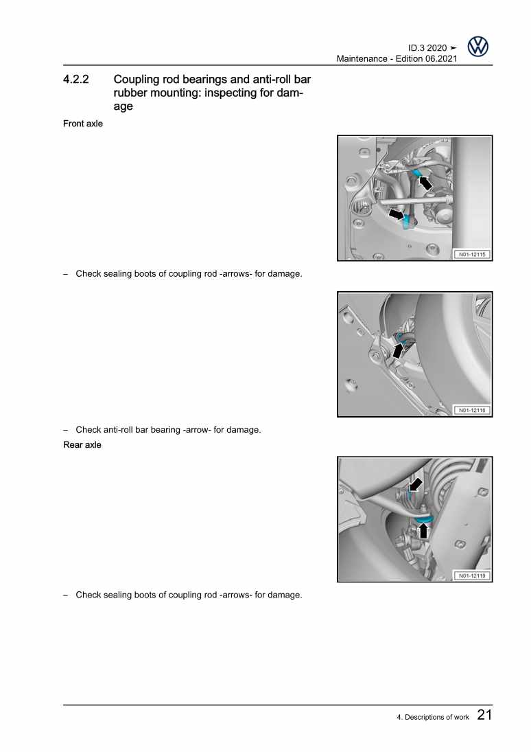
Maintenance

Beispielseite für Reparaturanleitung Maintenance

Für ID.3 (2020 >)

7,70 € Details

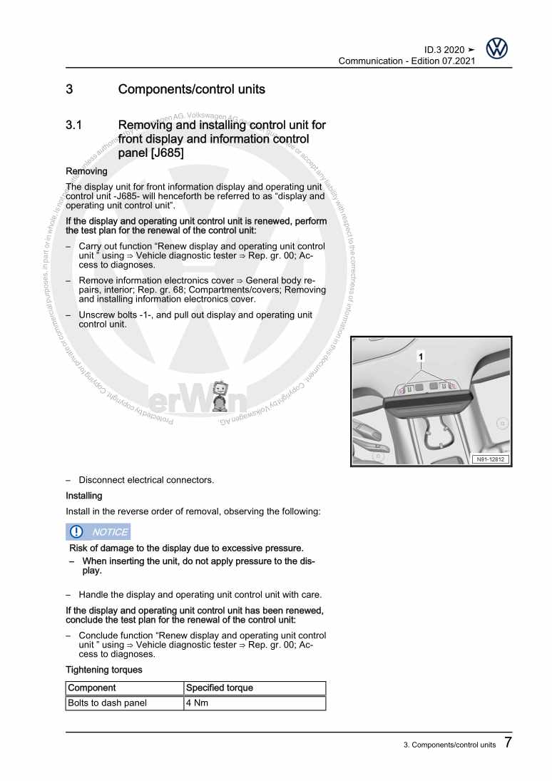
Communication

Beispielseite für Reparaturanleitung Communication

Für ID.3 (2020 >)

5,36 € Details

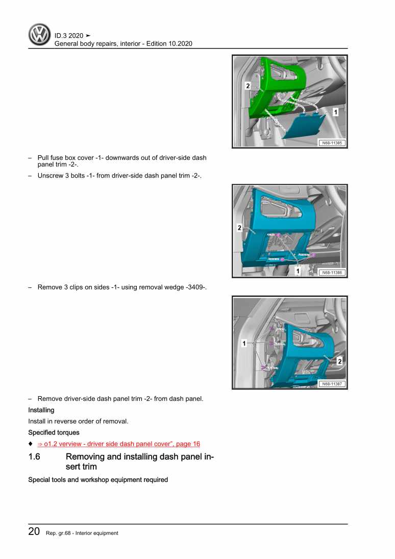
General body repairs, interior

Beispielseite für Reparaturanleitung General body repairs, interior

Für ID.3 (2020 >)

20,15 € Details

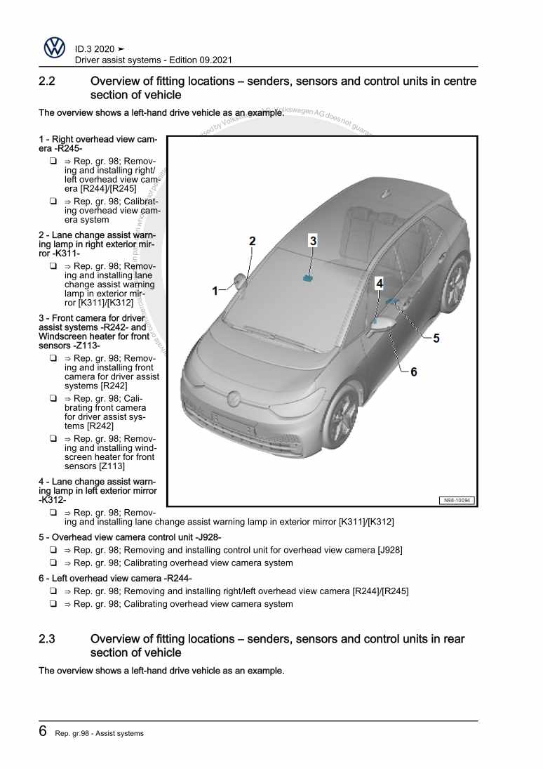
Driver assist systems

Beispielseite für Reparaturanleitung Driver assist systems

Für ID.3 (2020 >)

5,95 € Details

Body Repairs

Beispielseite für Reparaturanleitung Body Repairs

Für ID.3 (2020 >)

24,51 € Details

1-speed gearbox 0MH

Beispielseite für Reparaturanleitung 1-speed gearbox 0MH

Für ID.3 (2020 >)

4,51 € Details

Electric drive

Beispielseite für Reparaturanleitung Electric drive

Für ID.3 (2020 >)

18,51 € Details

Electric drive system, motor control unit, EBJD, From March 2020

Beispielseite für Reparaturanleitung Electric drive system, motor control unit, EBJD, From March 2020

Für ID.3 (2020 >)

49,15 € Details

Electrical system

Beispielseite für Reparaturanleitung Electrical system

Für ID.3 (2020 >)

15,16 € Details

Vehicle-specific paint information

Beispielseite für Reparaturanleitung Vehicle-specific paint information

Für ID.3 (2020 >)

6,29 € Details

Unsere Best Seller

Schon gewusst? Wir bieten auch originale Autoteile an.

Autoteil 5Q0825271A Abdeckung

5Q0825271A

Abdeckung

5,41 €

Details
Autoteil 8E0201263G Kuppl.Stck

8E0201263G

Kuppl.Stck

16,63 €

Details
Autoteil 04E145853E Buegel

04E145853E

Buegel

8,90 €

Details
Autoteil 0B5398009F Rep.Satz

0B5398009F

Rep.Satz

450,24 €

Details
Autoteil 8E0201220AF Kraftleitu

8E0201220AF

Kraftleitu

94,56 €

Details

Eigendiagnose für Automatisches Getriebe 09A - 5 Gang

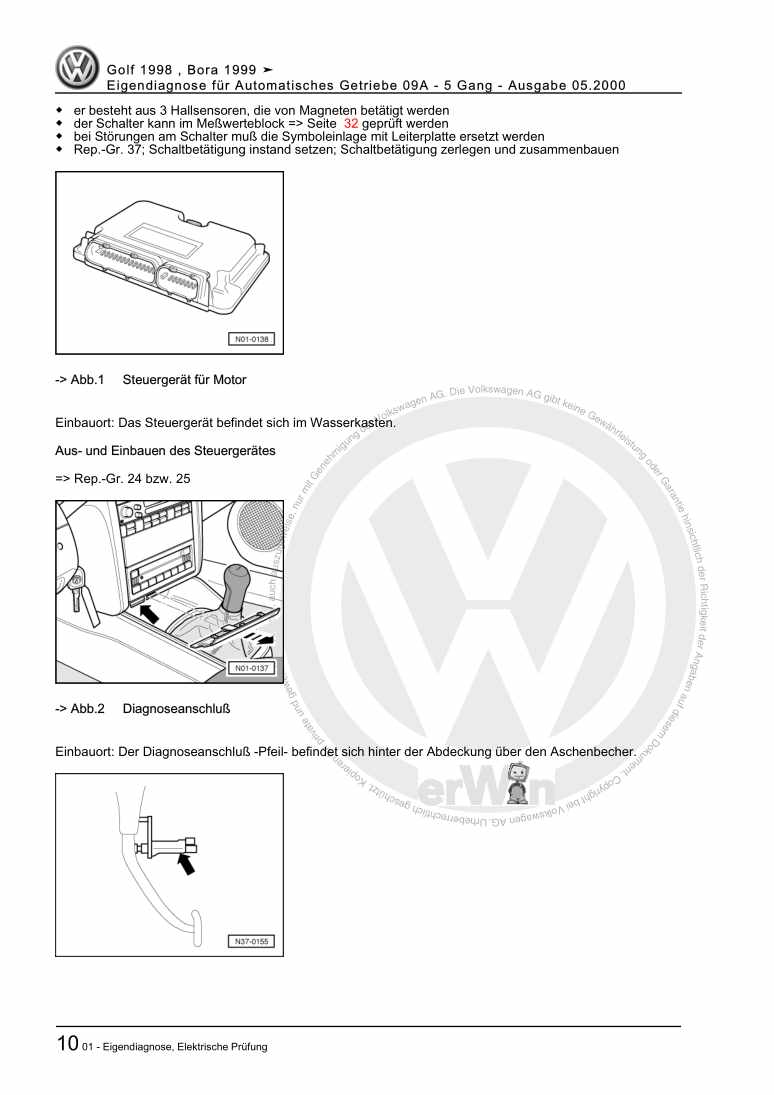
Beispielseite für Reparaturanleitung Eigendiagnose für Automatisches Getriebe 09A - 5 Gang

Für Bora / Bora Variant / Golf / Golf Variant (1998 - 2006)

6,00 € Details

7 Gang-Doppelkupplungsgetriebe 0GC Volkswagen R GmbH

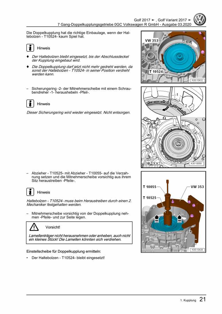
Beispielseite für Reparaturanleitung 7 Gang-Doppelkupplungsgetriebe 0GC Volkswagen R GmbH

Für Golf VII (2017) / Golf (2017)

10,54 € Details

Fahrwerk, Achsen, Lenkung

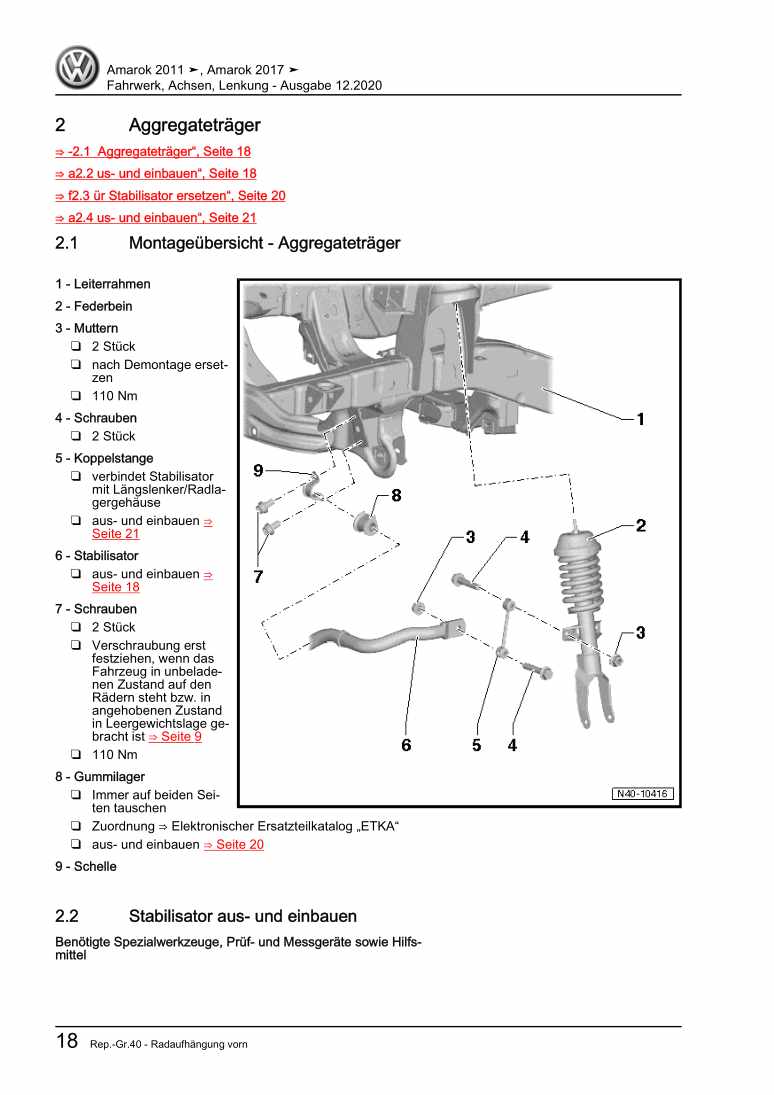
Beispielseite für Reparaturanleitung Fahrwerk, Achsen, Lenkung

Für Amarok (2011) / Amarok (2013) / Amarok (2017 >) / Amarok (2017)

15,68 € Details

image/svg+xml Über Clonck

Originale Reparaturanleitungen und Ersatzteile

Unsere Reparaturanleitungen sind Originale, kommen direkt von Volkswagen und erfüllen die höchsten Qualitätsstandards.

In unserem Originalteile-Shop verkaufen wir hochwertige Originalersatzteile der Fahrzeughersteller. Mithilfe der Suche gibst du die gewünschte Teilenummer (OE-Nummer) ein und bestellst schnell und einfach das benötigte Ersatzteil.

Höchste Qualitätsstandards

Bei Clonck wollen wir Autoschrauber und Kfz-Profis glücklich machen. Aus diesem Grund findest du bei Clonck ausschließlich professionelle und hochwertige Reparaturanleitungen, mit deren Hilfe du dein Fahrzeug fachgerecht reparieren kannst.

Unsere Partner

Autohaus Schmidt GmbH
Automag GmbH Filiale Laim
KFZ-VERLAG GmbH
Zimpel und Franke GmbH

Clonck: Der Autoreparatur-Shop - gibt's auch als App!

Clonck App Logo Play Store

Clonck: Passende Autoteile für deine Autoreparatur

4,5 90

Mit Clonck bestellst du die richtigen Originalersatzteile im Handumdrehen.

  • Fahrzeugmodell hinzufügen
  • Baugruppe auswählen
  • Fahrzeug-Identifizierungsnummer (FIN) eingeben
  • Über 5.000 originale Reparaturanleitungen einsehen
Jetzt App starten
Clonck App Preview Auto Mobiltelefon Autoteile