Technical data
11 Safety information
11.1 Safety regulations for working on fuel supply
11.2 Safety measures when working on vehicles with a start/stop system
21.4 Safety precautions when working on the cooling system
21.5 Safety precautions when working on the SCR system
32 Identification
42.1 Engine number/engine data
43 Repair instructions
63.1 Rules for cleanliness
63.2 Adapting learnt value for SCR system
63.3 Foreign objects in engine
63.4 Contact corrosion
73.5 Routing and attachment of lines
73.6 Fitting radiator and condensers
7Removing and installing engine
81 Removing and installing engine
81.1 Removing engine
81.2 Separating engine and gearbox
181.3 Securing engine on engine and gearbox support
191.4 Installing engine
212 Assembly mountings
252.1 Assembly overview - assembly mountings
252.2 Removing and installing engine mounting
272.3 Removing and installing gearbox mounting
282.4 Removing and installing pendulum support
292.5 Supporting engine in installation position
302.6 Adjusting assembly mountings
352.7 Checking adjustment of assembly mountings (engine and gearbox mountings)
363 Engine cover panel
373.1 Removing and installing engine cover
37Crankshaft group
381 Cylinder block (pulley end)
381.1 Assembly overview - cylinder block (pulley end)
381.2 Assembly overview - sealing flange, belt pulley end
401.3 Removing and installing poly-V belt
401.4 Removing and installing tensioner for poly V-belt
421.5 Removing and installing vibration damper
421.6 Removing and installing bracket for ancillaries
431.7 Removing and installing engine support
441.8 Removing and installing sealing flange on pulley end
452 Cylinder block, gearbox end
482.1 Assembly overview - cylinder block, gearbox end
482.2 Removing and installing flywheel
492.3 Removing and installing sealing flange on gearbox side
503 Crankshaft
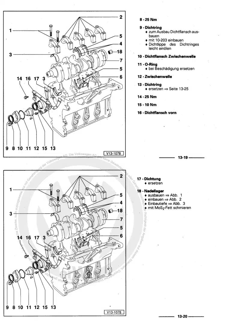
593.1 Assembly overview - crankshaft
593.2 Crankshaft dimensions
603.3 Renewing needle bearing in crankshaft
603.4 Measuring axial clearance of crankshaft
624 Pistons and conrods
644.1 Assembly overview - pistons and conrods
644.2 Removing and installing pistons
664.3 Measuring piston projection at TDC
674.4 Checking pistons and cylinder bores
694.5 Separating new conrod
714.6 Checking radial clearance of conrods
714.7 Removing and installing oil spray jets
71Cylinder head, valve gear
731 Cylinder head
731.1 Assembly overview - cylinder head
731.2 Assembly overview - cylinder head cover
751.3 Removing and installing cylinder head
771.4 Removing and installing cylinder head cover
871.5 Removing and installing injector seals
891.6 Removing and installing camshaft housing
911.7 Checking compression
952 Toothed belt drive
972.1 Assembly overview - toothed belt cover
972.2 Assembly overview - toothed belt
982.3 Removing and installing toothed belt guard
992.4 Removing and installing toothed belt
1022.5 Removing toothed belt from camshaft
1133 Valve gear
1183.1 Assembly overview - valve gear
1183.2 Measuring axial play of camshaft
1213.3 Removing and installing camshaft oil seal
1223.4 Removing and installing camshaft adjuster
1233.5 Removing and installing camshaft control valve 1 N205
1263.6 Removing control valve from and installing on inlet camshaft control valve 1 N205
1273.7 Checking hydraulic compensation elements
1293.8 Removing and installing valve stem seals
1304 Inlet and exhaust valves
1374.1 Checking valve guides
1374.2 Checking valves
1384.3 Valve dimensions
138Lubrication
1391 Sump, oil pump
1391.1 Assembly overview - sump/oil pump
1391.2 Engine oil:
1441.3 Removing and installing sump
1441.4 Removing and installing lower part of sump
1471.5 Removing and installing upper part of sump
1511.6 Removing and installing oil pump
1551.7 Removing and installing oil level and oil temperature sender G266
1562 Engine oil cooler
1582.1 Removing and installing engine oil cooler
1583 Oil filter, oil pressure switch
1593.1 Assembly overview - oil filter housing, oil pressure switch
1593.2 Removing and installing oil pressure switch F1
1603.3 Removing and installing oil pressure switch for reduced oil pressure F378
1613.4 Checking oil pressure
1623.5 Removing and installing oil filter housing
1623.6 Removing and installing oil pressure regulating valve N428
164Cooling
1661 Cooling system/coolant
1661.1 Connection diagram - coolant hoses
1661.2 Assembly overview - engine preheater
1681.3 Checking cooling system for leaks
1681.4 Draining and adding coolant
1702 Coolant pump, regulation of cooling system
1762.1 Assembly overview - coolant pump, thermostat
1762.2 Assembly overview - electric coolant pump
1782.3 Assembly overview - coolant temperature sender
1832.4 Removing and installing electric coolant pump
1842.5 Removing and installing coolant pump
1962.6 Removing and installing thermostat
1972.7 Checking thermostat
1972.8 Removing and installing coolant valve for cylinder head N489
1982.9 Removing and installing coolant temperature sender G62
1982.10 Removing and installing radiator outlet coolant temperature sender G83
1993 Coolant pipes
2013.1 Assembly overview - coolant pipes
2013.2 Removing and installing coolant pipes
2024 Radiator, radiator fan
2124.1 Assembly overview - radiator/radiator fan
2124.2 Removing and installing radiator
2144.3 Removing and installing water radiator for charge air cooling circuit
2154.4 Removing and installing radiator cowl with radiator fan
2184.5 Removing and installing radiator fan
219Turbocharging/supercharging
2201 Exhaust turbocharger
2201.1 Assembly overview - turbocharger
2201.2 Removing and installing turbocharger
2221.3 Renewing vacuum unit for turbocharger
2261.4 Removing and installing connection for turbocharger
2312 Charge air system
2332.1 Assembly overview - charge air system
2332.2 Removing and installing charge pressure sender G31
2352.3 Checking charge air system for leaks
235Mixture preparation - injection
2381 Injection system
2381.1 Schematic overview - fuel system
2381.2 Overview of fitting locations - injection system
2391.3 Filling/bleeding fuel system
2451.4 Checking fuel system for leaks
2452 Vacuum system
2462.1 Connection diagram - vacuum system
2462.2 Checking vacuum system
2463 Injectors/high-pressure accumulator (rail)
2483.1 Assembly overview - injectors
2483.2 Assembly overview - fuel rail
2503.3 Adapting correction values for injectors
2513.4 Testing injectors
2513.5 Checking return flow rate of injectors with engine running
2513.6 Checking return flow rate of injectors at starter speed
2543.7 Testing jammed-open injectors
2553.8 Removing and installing injectors
2563.9 Removing and installing high-pressure lines
2593.10 Removing and installing fuel rail
2614 Air filter
2634.1 Assembly overview - air filter housing
2634.2 Removing and installing air filter housing
2645 Intake manifold
2675.1 Assembly overview - intake manifold
2675.2 Removing and installing intake manifold
2695.3 Removing and installing throttle valve module J338
2726 Senders and sensors
2756.1 Removing and installing fuel pressure regulating valve N276
2756.2 Checking fuel pressure regulating valve N276
2816.3 Removing and installing fuel pressure sender G247
2826.4 Removing and installing air mass meter G70
2836.5 Removing and installing pressure differential sender G505
2856.6 Removing and installing exhaust gas pressure sensor 1 G450
2866.7 Removing and installing NOx sender 2 G687
2876.8 Removing and installing NOx sender G295
2896.10 Removing and installing fuel temperature sender G81
2907 Engine control unit
2937.1 Removing and installing engine (motor) control unit J623
2938 High-pressure pump
2978.1 Assembly overview - high-pressure pump
2978.2 Removing and installing high-pressure pump
2979 Lambda probe
3019.1 Assembly overview - Lambda probe
3019.2 Removing and installing Lambda probe
303Exhaust system
3041 Exhaust pipes and silencers
3041.1 Assembly overview - silencers
3041.2 Assembly overview - front exhaust pipe
3061.3 Removing and installing front exhaust pipe
3071.4 Separating exhaust pipes from silencers
3081.5 Removing and installing rear silencer
3091.6 Aligning exhaust system free of stress
3101.7 Check exhaust system for leaks
3111.8 Align end exhaust pipes
3112 Exhaust gas cleaning
3122.1 Assembly overview - emission control
3122.2 Removing and installing emission control module
3142.3 Removing and installing exhaust flap control unit J883
3203 SCR system (selective catalytic reduction)
3213.1 Assembly overview - tank for reducing agent
3213.2 Assembly overview - reducing agent delivery line
3233.3 Assembly overview - delivery module for reducing agent
3243.4 Assembly overview - injector for reducing agent
3253.5 Removing and installing reducing agent tank
3263.6 Disconnecting reducing agent supply line
3293.7 Removing and installing delivery module for reducing agent
3313.8 Removing and installing injector for reduction agent N474
3333.9 Removing and installing control unit for reducing-agent heater J891
3353.10 Draining reducing agent tank
3364 Exhaust gas temperature regulation
3394.1 Assembly overview - exhaust gas temperature regulation
3394.2 Removing and installing exhaust gas temperature sender 1 G235
3424.3 Removing and installing exhaust gas temperature sender 2 G448
3434.4 Removing and installing exhaust gas temperature sender 3 G495
3464.5 Removing and installing exhaust gas temperature sender 4 G648
3485 Exhaust gas recirculation
3515.1 Assembly overview - exhaust gas recirculation
3515.2 Assembly overview - exhaust gas recirculation control motor V338
3535.3 Removing and installing exhaust gas recirculation cooler
3535.4 Checking exhaust gas recirculation cooler for leaks
3565.5 Removing and installing exhaust gas recirculation control motor V338
3585.6 Removing and installing exhaust gas recirculation control motor 2 V339
3595.7 Removing and installing exhaust gas recirculation temperature sensor G98
361Glow plug system
3641 Glow plug system
3641.1 Assembly overview - glow plug system
3641.2 Removing and installing glow plug
3661.3 Removing and installing automatic glow period control unit J179
3681.4 Removing and installing Hall sender G40
3691.5 Removing and installing engine speed sender G28
369