DER AUTOREPARATUR-SHOP
0
Home » Anleitungen » 4-cyl. direct injection engine (2.0 l 4V turbocharger, toothed belt drive)
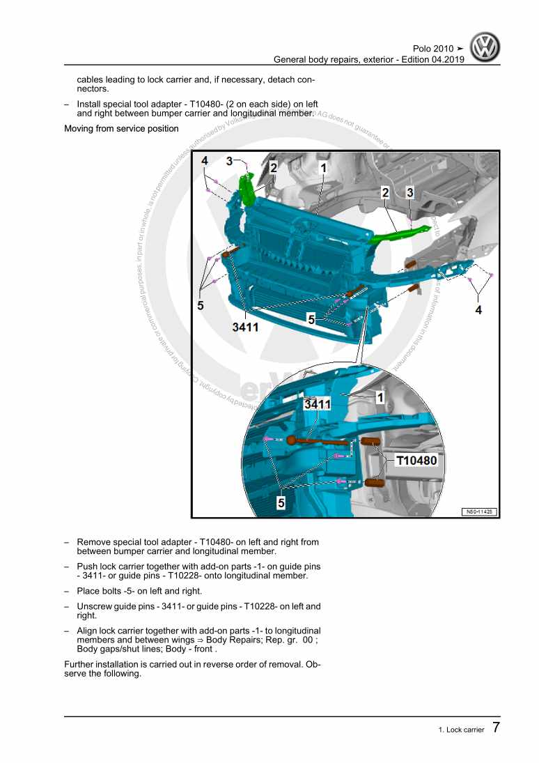
  • Beispielseite für Reparaturanleitung 4-cyl. direct injection engine (2.0 l 4V turbocharger, toothed belt drive)
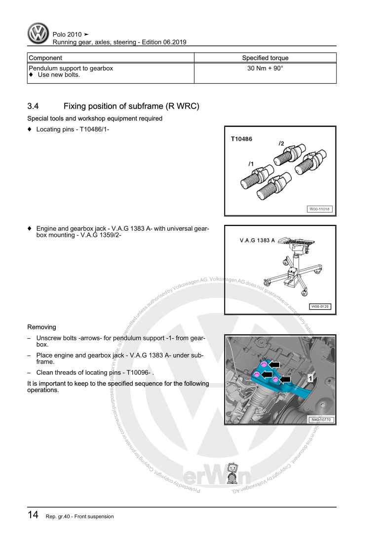
  • Beispielseite für Reparaturanleitung 2 4-cyl. direct injection engine (2.0 l 4V turbocharger, toothed belt drive)
  • Beispielseite für Reparaturanleitung 3 4-cyl. direct injection engine (2.0 l 4V turbocharger, toothed belt drive)

4-cyl. direct injection engine (2.0 l 4V turbocharger, toothed belt drive)

Für Polo A05

Original VW-Reparaturanleitung


19,94 €inkl. 7% MwSt.

  • Deutsch
  • English

Sofort als Download verfügbar

Sprache: English

Digitale PDF Version

16.970 KB

246 Seiten

Detaillierte technische Daten

Sofort lesbar

Diese Reparaturanleitung umfasst: Removing and installing engine, Assembly mountings, Engine cover panel, Cylinder block (pulley end), Crankshaft, Pistons and conrods, Toothed belt drive, Valve gear, Sump, oil pump, Oil filter, oil pressure switch, Coolant pump, regulation of cooling system, Radiator, radiator fan, Turbocharger, Intake manifold, Lambda probe und Exhaust pipes, silencers. Mehr anzeigen
Sichere Zahlung per PayPal, Kreditkarte, Lastschrift, Sofort-Überweisung oder Giropay
PayPal Logo SEPA Lastschrift Logo Giropay Logo Sofort Überweisung Logo

Reparaturanleitung Polo A05 4-cyl. direct injection engine pdf Download mit dem Inhalt:

Kapitelübersicht

  • Technical data
    1
  • 1 Engine number, engine data
    1
  • 2 Safety precautions
    2
  • 2.1 Safety precautions when working on fuel supply system
    2
  • 2.2 Safety precautions when working on ignition system
    2
  • 2.3 Releasing pressure in high-pressure area
    3
  • 3 General repair notes
    5
  • 3.1 Rules for cleanliness
    5
  • 3.2 Foreign objects in engine
    5
  • Removing and installing engine
    6
  • 1 Removing and installing engine
    6
  • 1.1 Removing engine
    6
  • 1.2 Separating engine and gearbox
    15
  • 1.3 Securing engine on engine and gearbox support
    16
  • 1.4 Installing engine
    18
  • 2 Assembly mountings
    21
  • 2.1 Assembly overview - assembly mountings
    21
  • 2.2 Removing and installing engine mounting
    22
  • 2.3 Removing and installing gearbox mounting
    23
  • 2.4 Removing and installing pendulum support
    26
  • 2.5 Supporting engine in installation position
    26
  • 3 Engine cover panel
    29
  • 3.1 Removing and installing engine cover panel
    29
  • Crankshaft group
    30
  • 1 Cylinder block (pulley end)
    30
  • 1.1 Assembly overview - poly V-belt drive
    30
  • 1.2 Assembly overview – sealing flange, pulley end
    31
  • 1.3 Removing and installing poly V-belt
    32
  • 1.4 Removing and installing tensioner for poly V-belt
    34
  • 1.5 Removing and installing bracket for ancillaries
    34
  • 1.6 Removing and installing vibration damper
    35
  • 1.7 Renewing crankshaft oil seal - belt pulley end
    36
  • 1.8 Removing and installing sealing flange on pulley end
    38
  • 2 Cylinder block, gearbox end
    42
  • 2.1 Assembly overview - cylinder block, gearbox end
    42
  • 2.2 Removing and installing flywheel
    43
  • 2.3 Removing and installing sealing flange on gearbox side
    44
  • 3 Crankshaft
    47
  • 3.1 Assembly overview - crankshaft
    47
  • 3.2 Crankshaft dimensions
    49
  • 3.3 Measuring axial clearance of crankshaft
    49
  • 3.4 Measuring radial clearance of crankshaft
    50
  • 3.5 Removing and installing drive chain sprocket
    51
  • 4 Pistons and conrods
    54
  • 4.1 Assembly overview - pistons and conrods
    54
  • 4.2 Removing and installing pistons
    55
  • 4.3 Checking piston and cylinder bore
    57
  • 4.4 Checking radial clearance of conrods
    58
  • Cylinder head, valve gear
    60
  • 1 Cylinder head
    60
  • 1.1 Assembly overview - cylinder head
    60
  • 1.2 Removing and installing cylinder head
    62
  • 1.3 Removing and installing cylinder head cover
    68
  • 1.4 Checking compression
    70
  • 1.5 Removing and installing vacuum pump
    71
  • 2 Toothed belt drive
    73
  • 2.1 Assembly overview - toothed belt
    73
  • 2.2 Removing and installing toothed belt
    74
  • 3 Valve gear
    79
  • 3.1 Assembly overview - valve gear
    79
  • 3.2 Measuring axial play of camshaft
    81
  • 3.3 Measuring radial play of camshaft
    82
  • 3.4 Removing and installing camshaft oil seal
    83
  • 3.5 Removing and installing camshaft adjuster
    85
  • 3.6 Removing and installing inlet camshaft control valve 1 N205
    89
  • 3.7 Removing and installing camshaft
    90
  • 3.8 Removing and installing valve stem seals
    94
  • 4 Inlet and exhaust valves
    103
  • 4.1 Checking valve guides
    103
  • 4.2 Checking valves
    104
  • 4.3 Valve dimensions
    104
  • Lubrication
    105
  • 1 Sump, oil pump
    105
  • 1.1 Assembly overview - sump, oil pump
    105
  • 1.2 Engine oil
    106
  • 1.3 Removing and installing sump
    106
  • 1.4 Removing and installing oil level and oil temperature sender G266
    110
  • 2 Engine oil cooler
    111
  • 2.1 Removing and installing engine oil cooler
    111
  • 3 Oil filter, oil pressure switch
    113
  • 3.1 Assembly overview - oil filter housing, oil pressure switch
    113
  • 3.2 Draining oil filter housing
    114
  • 3.3 Removing and installing oil filter housing
    116
  • 3.4 Removing and installing oil pressure switch F1
    116
  • 3.5 Checking oil pressure and oil pressure switch
    118
  • 4 Balancer shaft module
    120
  • 4.1 Assembly overview - balancer shaft module
    120
  • 4.2 Removing and installing balance shaft module
    121
  • Cooling
    127
  • 1 Cooling system, coolant
    127
  • 1.1 Coolant hose schematic diagram
    127
  • 1.2 Draining and filling coolant
    128
  • 1.3 Checking cooling system for leaks
    133
  • 2 Coolant pump, regulation of cooling system
    135
  • 2.1 Assembly overview - coolant pump, thermostat
    135
  • 2.2 Assembly overview - electric coolant pump
    136
  • 2.3 Removing and installing continued coolant circulation pump V51
    136
  • 2.4 Removing and installing coolant pump
    137
  • 2.5 Removing and installing thermostat
    138
  • 2.6 Removing and installing coolant temperature sender G62
    139
  • 3 Coolant pipes
    142
  • 3.1 Assembly overview - coolant pipes
    142
  • 3.2 Removing and installing coolant pipes
    143
  • 3.3 Removing and installing front right coolant pipe
    145
  • 4 Radiator, radiator fan
    147
  • 4.1 Assembly overview - radiator, radiator fan
    147
  • 4.2 Removing and installing radiator
    148
  • 4.3 Removing and installing radiator cowling with radiator fan
    150
  • 4.4 Removing and installing radiator fan
    152
  • Turbocharging/supercharging
    153
  • 1 Turbocharger
    153
  • 1.1 Assembly overview - turbocharger
    153
  • 1.2 Removing and installing turbocharger
    156
  • 1.3 Checking vacuum unit for turbocharger
    161
  • 1.4 Renewing vacuum unit for turbocharger
    163
  • 1.5 Adjusting vacuum unit for turbocharger
    163
  • 2 Charge air system
    168
  • 2.1 Schematic overview - charge air system
    168
  • 2.2 Assembly overview - charge air system
    169
  • 2.3 Assembly overview - charge-air hose connections
    171
  • 2.4 Removing and installing charge air cooler
    172
  • 2.5 Removing and installing charge pressure sender G31
    173
  • 2.6 Checking charge air system for leaks
    173
  • Mixture preparation - injection
    176
  • 1 Injection system
    176
  • 1.1 Overview of fitting locations - injection system
    176
  • 2 Air filter
    185
  • 2.1 Assembly overview - air filter housing
    185
  • 2.2 Removing and installing air filter housing
    186
  • 3 Intake manifold
    188
  • 3.1 Assembly overview - intake manifold
    188
  • 3.2 Assembly overview - intake manifold with fuel rail
    190
  • 3.3 Removing and installing intake manifold with fuel rail
    191
  • 3.4 Removing and installing throttle valve module J338
    194
  • 3.5 Cleaning throttle valve module
    196
  • 3.6 Removing and installing intake manifold flap motor V157
    197
  • 3.7 Checking intake manifold change-over
    198
  • 3.8 Checking double non-return valve
    200
  • 4 High-pressure pump
    202
  • 4.1 Assembly overview - high-pressure pump
    202
  • 4.2 Removing and installing high-pressure pump
    203
  • 5 Injectors
    205
  • 5.1 Removing and installing fuel rail
    205
  • 5.2 Removing and installing injectors
    206
  • 5.3 Renewing seals on injectors
    209
  • 5.4 Cleaning injectors
    211
  • 6 Senders and sensors
    213
  • 6.2 Removing and installing air mass meter G70
    214
  • 6.3 Removing and installing fuel pressure sender G247
    214
  • 6.4 Checking fuel pressure sender G247
    216
  • 7 Lambda probe
    219
  • 7.1 Assembly overview - Lambda probe
    219
  • 7.2 Removing and installing Lambda probe G39
    219
  • 7.3 Removing and installing Lambda probe after catalytic converter G130
    221
  • 8 Engine control unit
    223
  • 8.1 Removing and installing engine control unit J623
    223
  • Exhaust system
    225
  • 1 Exhaust pipes, silencers
    225
  • 1.1 Assembly overview - silencers
    225
  • 1.2 Separating exhaust pipes, silencers
    226
  • 1.3 Aligning exhaust system free of stress
    227
  • 1.4 Checking exhaust system for leaks
    228
  • 2 Emission control
    229
  • 2.1 Assembly overview - emission control
    229
  • 2.2 Removing and installing catalytic converter
    230
  • 3 Exhaust manifold
    233
  • Ignition system
    234
  • 1 Ignition system
    234
  • 1.1 Assembly overview - ignition system
    234
  • 1.2 Test data, spark plugs
    235
  • 1.3 Removing and installing ignition coils with output stage
    236
  • 1.4 Removing and installing knock sensor 1 G61
    237
  • 1.5 Removing and installing knock sensor 2 G66
    238
  • 1.6 Removing and installing Hall sender G40
    239
  • 1.7 Removing and installing engine speed sender G28
    239
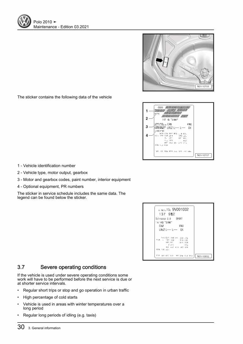
Hersteller­bezeichnung 4-cyl. direct injection engine (2.0 l 4V turbocharger, toothed belt drive)
Hersteller Volkswagen
Passend für Polo A05 (2010)
Passende Autotypen 6R1
Motor­kennbuchstaben CDLJ
Kategorie Reparaturanleitung

Im Moment sind noch keine Bewertungen für dieses Produkt vorhanden.

Ähnliche Reparaturanleitungen

Maintenance

Beispielseite für Reparaturanleitung Maintenance

Für Polo A05 (2010)

18,65 € Details

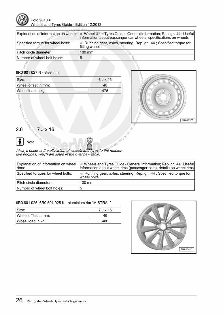
Wheels and Tyres Guide

Beispielseite für Reparaturanleitung Wheels and Tyres Guide

Für Polo A05 (2010)

5,67 € Details

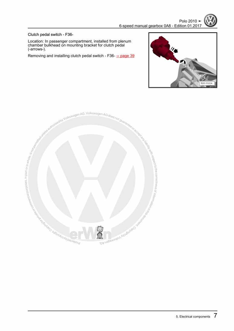
6-speed manual gearbox 0A8

Beispielseite für Reparaturanleitung 6-speed manual gearbox 0A8

Für Polo A05 (2010)

16,55 € Details

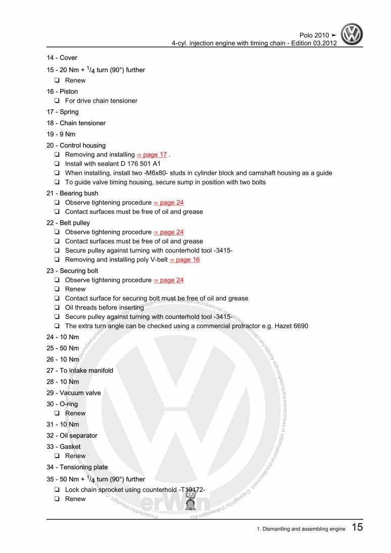
4-cyl. injection engine with timing chain

Beispielseite für Reparaturanleitung 4-cyl. injection engine with timing chain

Für Polo A05 (2010)

12,25 € Details

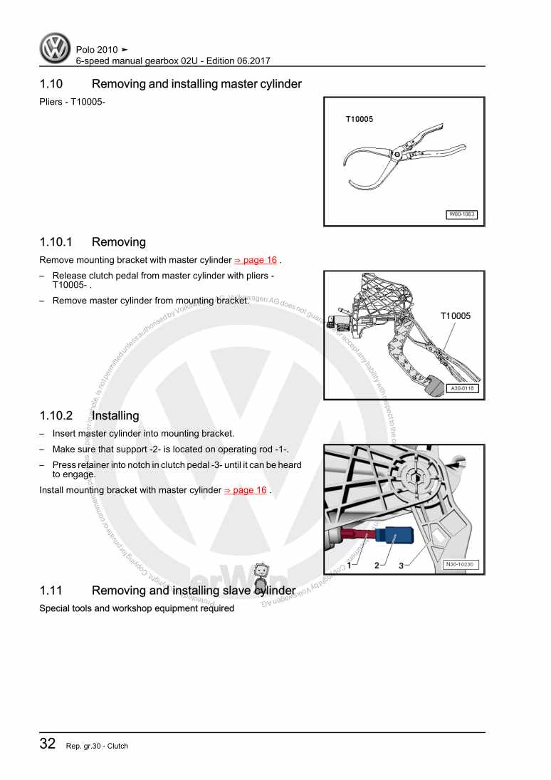
6-speed manual gearbox 02U

Beispielseite für Reparaturanleitung 6-speed manual gearbox 02U

Für Polo A05 (2010)

13,63 € Details

General body repairs, exterior

Beispielseite für Reparaturanleitung General body repairs, exterior

Für Polo A05 (2010)

33,78 € Details

Running gear, axles, steering

Beispielseite für Reparaturanleitung Running gear, axles, steering

Für Polo A05 (2010)

18,29 € Details

Electrical system

Beispielseite für Reparaturanleitung Electrical system

Für Polo A05 (2010)

25,58 € Details

Running gear, axles, steering

Beispielseite für Reparaturanleitung Running gear, axles, steering

Für Polo A05 (2010)

18,44 € Details

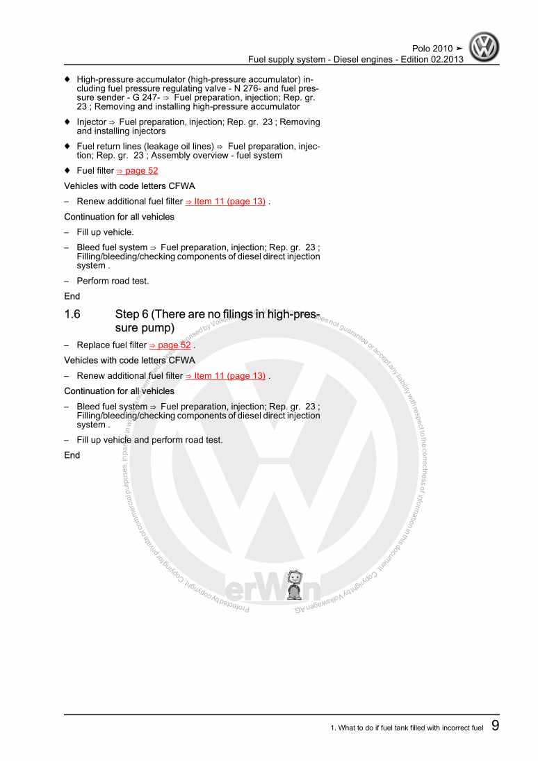
Fuel supply system - Diesel engines

Beispielseite für Reparaturanleitung Fuel supply system - Diesel engines

Für Polo A05 (2010)

8,02 € Details

Unsere Best Seller

Schon gewusst? Wir bieten auch originale Autoteile an.

Autoteil 4G0919268H Aufnahme

4G0919268H

Aufnahme

21,35 €

Details
Autoteil 5Q0713128A Schalter

5Q0713128A

Schalter

46,12 €

Details
Autoteil 7H7067081 Gasdrfeder

7H7067081

Gasdrfeder

35,85 €

Details
Autoteil 8S0827990 Adapter

8S0827990

Adapter

67,54 €

Details
Autoteil 1S0823363F Stuetze

1S0823363F

Stuetze

19,43 €

Details

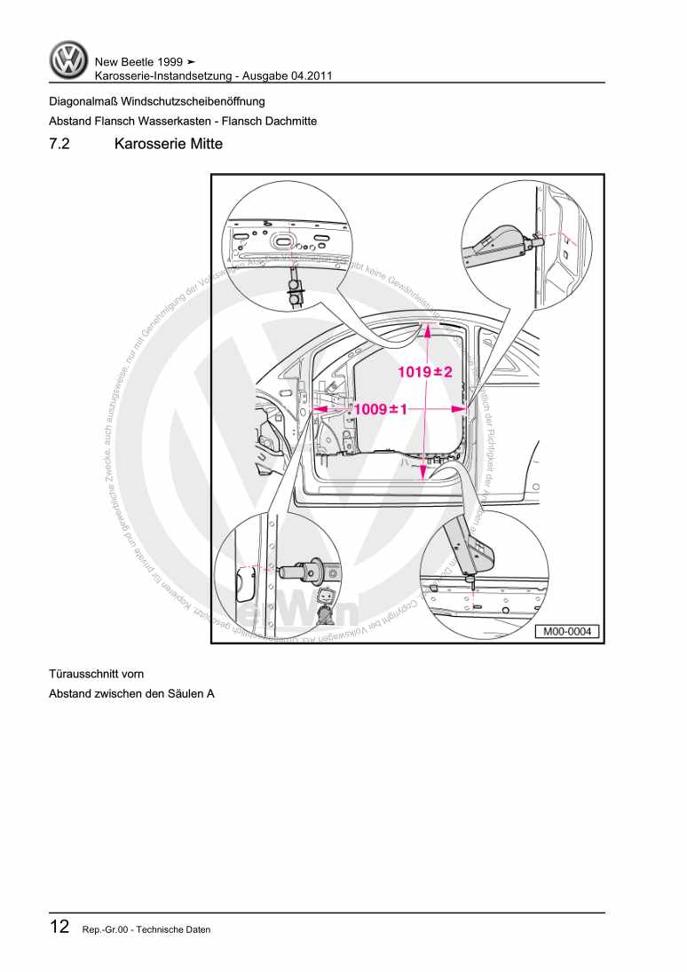
Karosserie-Instandsetzung

Beispielseite für Reparaturanleitung Karosserie-Instandsetzung

Für New Beetle / New Beetle (USA) (1998 - 2007) / New Beetle (Europe) (1999 - 2002)

10,12 € Details

Nr. 528: Der Erdgasantrieb im Golf/Golf Variant TGI BlueMotion

Beispielseite für Reparaturanleitung Nr. 528: Der Erdgasantrieb im Golf/Golf Variant TGI BlueMotion

5,26 € Details

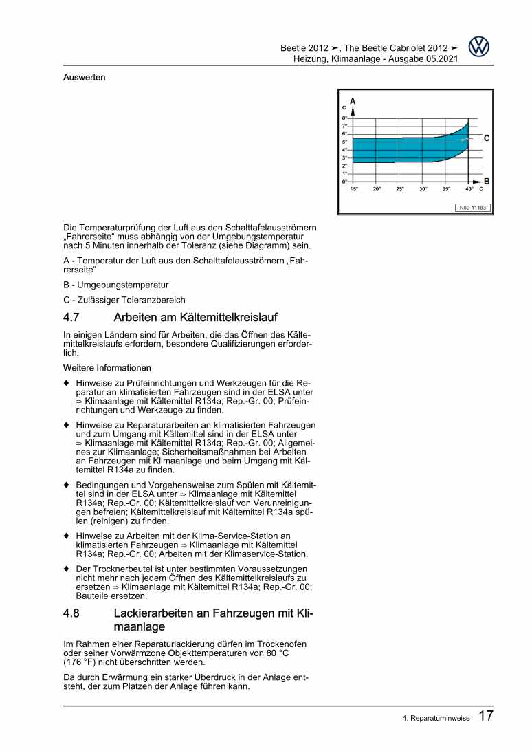
Heizung, Klimaanlage

Beispielseite für Reparaturanleitung Heizung, Klimaanlage

Für Beetle (NBL) Limousine (2012) / Beetle (NBC) Cabrio (2012)

15,89 € Details

image/svg+xml Über Clonck

Originale Reparaturanleitungen und Ersatzteile

Unsere Reparaturanleitungen sind Originale, kommen direkt von Volkswagen und erfüllen die höchsten Qualitätsstandards.

In unserem Originalteile-Shop verkaufen wir hochwertige Originalersatzteile der Fahrzeughersteller. Mithilfe der Suche gibst du die gewünschte Teilenummer (OE-Nummer) ein und bestellst schnell und einfach das benötigte Ersatzteil.

Höchste Qualitätsstandards

Bei Clonck wollen wir Autoschrauber und Kfz-Profis glücklich machen. Aus diesem Grund findest du bei Clonck ausschließlich professionelle und hochwertige Reparaturanleitungen, mit deren Hilfe du dein Fahrzeug fachgerecht reparieren kannst.

Unsere Partner

Autohaus Schmidt GmbH
Automag GmbH Filiale Laim
KFZ-VERLAG GmbH
Zimpel und Franke GmbH

Clonck: Der Autoreparatur-Shop - gibt's auch als App!

Clonck App Logo Play Store

Clonck: Passende Autoteile für deine Autoreparatur

4,5 90

Mit Clonck bestellst du die richtigen Originalersatzteile im Handumdrehen.

  • Fahrzeugmodell hinzufügen
  • Baugruppe auswählen
  • Fahrzeug-Identifizierungsnummer (FIN) eingeben
  • Über 5.000 originale Reparaturanleitungen einsehen
Jetzt App starten
Clonck App Preview Auto Mobiltelefon Autoteile