DER AUTOREPARATUR-SHOP
0
Home » Anleitungen » 3 - Cyl. injection engine
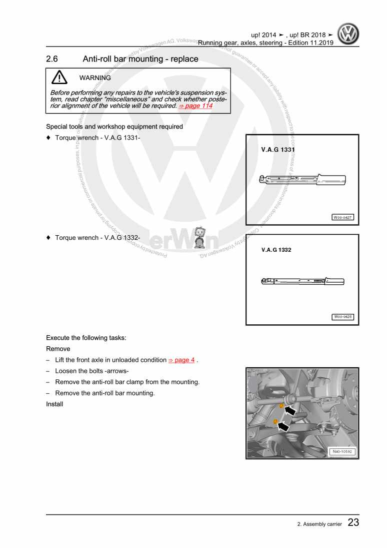
  • Beispielseite für Reparaturanleitung 3 - Cyl. injection engine
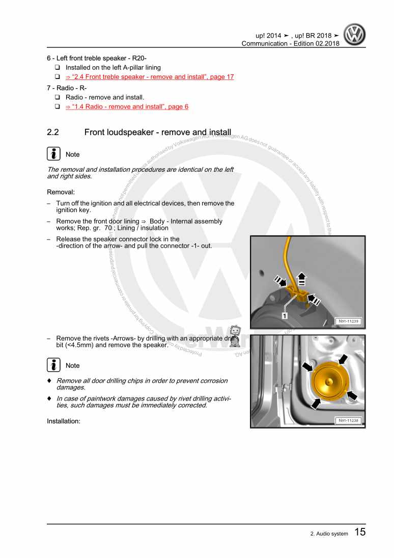
  • Beispielseite für Reparaturanleitung 2 3 - Cyl. injection engine
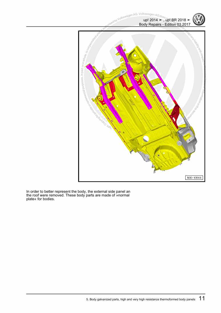
  • Beispielseite für Reparaturanleitung 3 3 - Cyl. injection engine
  • Beispielseite für Reparaturanleitung 3 - Cyl. injection engine
  • Beispielseite für Reparaturanleitung 2 3 - Cyl. injection engine
  • Beispielseite für Reparaturanleitung 3 3 - Cyl. injection engine

3 - Cyl. injection engine

Für VW UP / VW Up [BR]

Original VW-Reparaturanleitung


27,01 €inkl. 7% MwSt.

Sofort als Download verfügbar

Sprache: English

Digitale PDF Version

31.894 KB

350 Seiten

Detaillierte technische Daten

Sofort lesbar

Diese Reparaturanleitung umfasst: Engine - remove and install, Power-drive unit supports, Cylinder block (pulley side), Crankshaft, Toothed belt drive, Oil filter/ Oil pressure switch F1, Cooling system/coolant, Radiator/ Radiator fan V7, Fuel reservoir, Fuel pump (pre-supply pump) G6 / Fuel gauge sensor G, Quick-release fastener with button, Activated charcoal filter system, Engine power electronic adjustment (electronic accelerator), Injection valves, Air cleaner, Intake manifold und Lambda probe. Mehr anzeigen
Sichere Zahlung per PayPal, Kreditkarte, Lastschrift, Sofort-Überweisung oder Giropay
PayPal Logo SEPA Lastschrift Logo Giropay Logo Sofort Überweisung Logo

Reparaturanleitung VW UP / VW Up [BR] 3 - Cyl. injection engine pdf Download mit dem Inhalt:

Kapitelübersicht

  • Technical data
    1
  • 1 \--- Change history ---
    1
  • 2 Safety instructions
    2
  • 2.1 Safety measures regarding work on the fuel supply
    2
  • 2.2 Safety measures in test drives using testing and measurement devices
    3
  • 2.3 Safety measures when working on the cooling system
    4
  • 2.4 Safety measures when working on the ignition system
    5
  • 3 Identification
    6
  • 3.1 Engine number/engine characteristics
    6
  • 4 Repair instructions
    8
  • 4.1 Cleaning rules
    8
  • 4.2 General instructions
    8
  • 4.3 General repair instructions
    8
  • 4.4 Foreign bodies on the engine
    9
  • 4.5 Contact corrosion
    9
  • 4.6 Connection installation and fastening
    9
  • 4.7 Radiator and capacitor installation
    9
  • Removing and installing engine
    10
  • 1 Engine - remove and install
    10
  • 1.1 Engine - removal
    10
  • 1.2 Engine - separate gearbox
    18
  • 1.3 Secure the engine to the engine and gearbox swivelling stand
    20
  • 1.4 Engine - installation
    22
  • 2 Power-drive unit supports
    24
  • 2.1 Power unit brackets - assembly overview
    24
  • 2.2 Power unit bracket (engine side) - remove and install
    26
  • 2.3 Power-drive unit supports (gearbox side) - remove and install
    27
  • 2.4 Pendulum support (torque limiter) - remove and install
    30
  • 2.5 Support the engine in assembly position
    30
  • 2.6 Power-drive group support (engine side) - adjust
    33
  • 2.7 Additional notes and installation works in vehicles with air conditioning
    33
  • Crankshaft group
    35
  • 1 Cylinder block (pulley side)
    35
  • 1.1 Poly-V belt mechanism - assembly overview
    35
  • 1.2 Poly-V belt mechanism - assembly overview
    36
  • 1.3 Cylinder block (pulley side) - assembly overview
    37
  • 1.4 Poly-V belt - remove and install
    39
  • 1.5 Poly-V belt - remove and install
    41
  • 1.6 Poly-V belt tensioner - remove and install
    43
  • 1.7 Engine console - remove and install
    44
  • 1.8 Crankshaft pulley (vibration damper) - remove and install
    45
  • 1.9 Crankshaft seal (pulley side) - replace
    46
  • 2 Cylinder block (gearbox side)
    50
  • 2.1 Cylinder block (gearbox side) - assembly overview
    50
  • 2.2 Flywheel - remove and install
    51
  • 2.3 Crankshaft flange (flywheel side) - replace
    52
  • 3 Crankshaft
    61
  • 3.1 Crankshaft - dimensions
    61
  • 4 Pistons and conrods
    62
  • 4.1 Pistons and conrods - assembly overview
    62
  • 4.2 Pistons - remove and install
    64
  • 4.3 Pistons, rings, and cylinders - check
    65
  • 4.4 Conrod and cap (new part) - separate
    67
  • 4.5 Conrod radial clearance - check
    68
  • 4.6 Oil spray jet and valve - remove and install
    68
  • Cylinder head, valve gear
    70
  • 1 Cylinder head - assembly and disassembly
    70
  • 1.1 Cylinder head - assembly overview
    70
  • 1.2 Engine cylinder head - remove and install
    72
  • 1.3 Cylinder head cover with exhaust and inlet camshafts - remove and install
    78
  • 1.4 Compression - check
    87
  • 2 Toothed belt drive
    91
  • 2.1 Toothed belt - remove and install
    91
  • 2.2 Valve timing - check
    102
  • 2.3 Valve timing - adjust
    106
  • 3 Camshaft mechanism
    119
  • 3.1 Camshaft mechanism - assembly overview
    119
  • 3.2 Crankshaft - check axial clearance
    121
  • 3.3 Crankshaft seal - replace
    122
  • 3.4 Inlet camshaft regulator - remove and install
    138
  • 3.5 Exhaust camshaft sprocket - remove and install
    144
  • 3.6 Camshaft adjustment valve 1 N205 - remove and install
    149
  • 3.7 Valve stem sealant - replace
    149
  • 4 Inlet and exhaust valves
    156
  • 4.1 Valve guides - check
    156
  • 4.2 Valves - check
    156
  • 4.3 Valve dimensions
    157
  • Lubrication
    158
  • 1 Crankcase/oil pump
    158
  • 1.1 Crankcase/oil pump - assembly overview
    158
  • 1.2 Engine oil
    161
  • 1.3 Lower sump - remove and install
    162
  • 1.4 Upper crankcase - remove and install
    163
  • 1.5 Oil pump - remove and install
    167
  • 2 Engine crankcase ventilation
    170
  • 2.1 Engine crankcase ventilation - assembly overview
    170
  • 2.2 Crankcase ventilation device - remove and install
    171
  • 3 Oil filter/ Oil pressure switch F1
    173
  • 3.1 Oil pressure switch F1 - remove and install
    173
  • 3.2 Oil pressure and Oil pressure switch F1 - check
    174
  • 3.3 Oil filter - remove and install
    176
  • Cooling
    178
  • 1 Cooling system/coolant
    178
  • 1.1 Hose connection diagram for cooling system
    178
  • 1.2 Cooling system - check air-tightness
    178
  • 1.3 Coolant tank flap - check safety valve
    180
  • 1.4 Cooling system - drainage and replenishment
    181
  • 2 Water pump/coolant adjustment
    190
  • 2.1 Water pump - assembly overview
    190
  • 2.2 Water pump - remove and install
    192
  • 2.3 Thermostat valve - assembly overview
    196
  • 2.4 Thermostat valve - removal and installation
    198
  • 2.5 Water pump toothed belt - remove and install
    203
  • 2.6 Water pump sprocket - remove and install
    206
  • 2.7 Coolant temperature sensor G62 - remove and install
    207
  • 3 Radiator/ Radiator fan V7
    210
  • 3.1 Radiator/ Radiator fan V7 - assembly overview
    210
  • 3.2 Radiator - remove and install
    212
  • 3.3 Radiator fan V7 air deflector - remove and install
    215
  • 3.4 Radiator fan V7 - remove and install
    218
  • Fuel supply system
    221
  • 1 Fuel reservoir
    221
  • 1.1 Fuel tank - assembly overview
    221
  • 1.2 Cold start system components - remove and install
    225
  • 1.3 Fuel reservoir - remove and install
    226
  • 1.4 Fuel tank - drain
    230
  • 2 Fuel pump (pre-supply pump) G6 / Fuel gauge sensor G
    237
  • 2.2 Fuel pump (pre-supply pump) G6 / Fuel gauge sensor G - remove and install
    239
  • 2.3 Fuel gauge sensor G - remove and install
    243
  • 3 Quick-release fastener with button
    245
  • 3.1 Quick-release fastener with button - disconnect
    245
  • 4 Fuel filter
    249
  • 4.1 Fuel filter - remove and install
    249
  • 5 Activated charcoal filter system
    250
  • 5.1 Activated charcoal filter system - operation
    250
  • 5.2 Activated charcoal filter system - assembly overview
    251
  • 5.3 Fuel tank ventilation system - check
    252
  • 5.4 Activated charcoal filter - remove and install
    258
  • 6 Engine power electronic adjustment (electronic accelerator)
    263
  • 6.1 Accelerator pedal module (electric throttle) - assembly overview
    263
  • 6.2 Accelerator pedal module (electric throttle) - remove and install
    264
  • 7 Fuel pump (pre-supply pump) G6
    266
  • 7.1 Fuel pump (pre-supply pump) G6 - check
    266
  • Mixture preparation - injection
    287
  • 1 Injection system
    287
  • 1.1 Injection system - assembly overview
    287
  • 1.2 Combustion system - assembly overview
    290
  • 2 Injection valves
    292
  • 2.1 Fuel rail with injection valves - assembly overview
    292
  • 2.2 Injection valves - remove and install
    295
  • 2.3 Injection valves - check
    299
  • 3 Air cleaner
    305
  • 3.1 Air filter - assembly overview
    305
  • 3.2 Air filter - remove and install
    306
  • 4 Intake manifold
    307
  • 4.1 Intake manifold - assembly overview
    307
  • 4.2 Intake manifold - remove and install
    308
  • 4.3 Throttle butterfly valve control unit J338 - remove and install
    310
  • 4.4 Throttle valve control unit J338 - clean
    312
  • 5 Transmitters and sensors
    313
  • 6 Engine control unit J623
    315
  • 6.1 Engine control unit J623 - assembly overview
    315
  • 6.2 Engine control unit J623 - remove and install
    316
  • 6.3 Engine control unit J623 support - remove and install
    319
  • 7 Lambda probe
    320
  • 7.1 Lambda probe - remove and install
    320
  • Exhaust system
    324
  • 1 Silencer/exhaust pipes
    324
  • 1.1 Silencer - assembly overview
    324
  • 1.2 Silencer/exhaust pipes - separation
    325
  • 1.3 Silencer - remove and install
    326
  • 1.4 Exhaust system - check air-tightness
    328
  • 1.5 Double clamp - installation position
    329
  • 2 Exhaust system
    330
  • 2.1 Front exhaust pipe - assembly overview
    330
  • 2.2 Catalytic converter - remove and install
    331
  • Ignition system
    334
  • 1 Ignition system
    334
  • 1.1 Ignition system - assembly overview
    334
  • 1.2 Ignition coils with final power stage - assembly overview
    335
  • 1.3 Spark plugs Q - technical data
    336
  • 1.4 Ignition coil with final power stage - remove and install
    336
  • 1.5 Knock sensor 1 G61 - remove and install
    339
  • 1.6 Hall Sensor G40 - remove and install
    340
  • 1.7 Engine speed sensor G28 - remove and install
    341
Hersteller­bezeichnung 3 - Cyl. injection engine
Hersteller Volkswagen
Passend für VW UP (Brasilien ) (2014 >) / VW UP (Brasilien) (2014) / VW Up [BR] (2014 >)
Passende Autotypen 6A1, 6A6
Motor­kennbuchstaben CWRA
Kategorie Reparaturanleitung

Im Moment sind noch keine Bewertungen für dieses Produkt vorhanden.

Ähnliche Reparaturanleitungen

5 - Speed manual gearbox 0DF

Beispielseite für Reparaturanleitung 5 - Speed manual gearbox 0DF

Für VW UP (Brasilien ) (2014 >) / VW UP (Brasilien) (2014) / VW Up [BR] (2014 >)

12,40 € Details

Running gear, axles, steering

Beispielseite für Reparaturanleitung Running gear, axles, steering

Für VW UP (Brasilien ) (2014 >) / VW UP (Brasilien) (2014) / VW Up [BR] (2014 >)

14,14 € Details

Communication

Beispielseite für Reparaturanleitung Communication

Für VW UP (Brasilien ) (2014 >) / VW UP (Brasilien) (2014) / VW Up [BR] (2014 >)

4,88 € Details

Body Repairs

Beispielseite für Reparaturanleitung Body Repairs

Für VW UP (Brasilien ) (2014 >) / VW UP (Brasilien) (2014) / VW Up [BR] (2014 >)

22,54 € Details

Heating, air conditioning

Beispielseite für Reparaturanleitung Heating, air conditioning

Für VW UP (Brasilien ) (2014 >) / VW UP (Brasilien) (2014) / VW Up [BR] (2014 >)

7,89 € Details

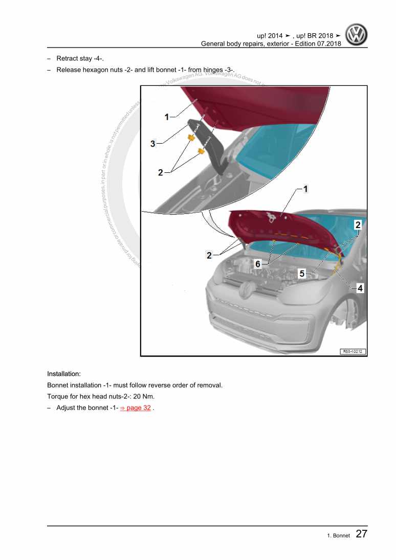
General body repairs, exterior

Beispielseite für Reparaturanleitung General body repairs, exterior

Für VW UP (Brasilien ) (2014 >) / VW UP (Brasilien) (2014) / VW Up [BR] (2014 >)

28,66 € Details

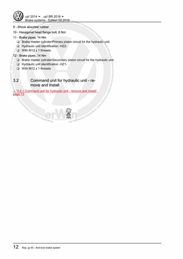
Brake systems

Beispielseite für Reparaturanleitung Brake systems

Für VW UP (Brasilien ) (2014 >) / VW UP (Brasilien) (2014) / VW Up [BR] (2014 >)

8,15 € Details

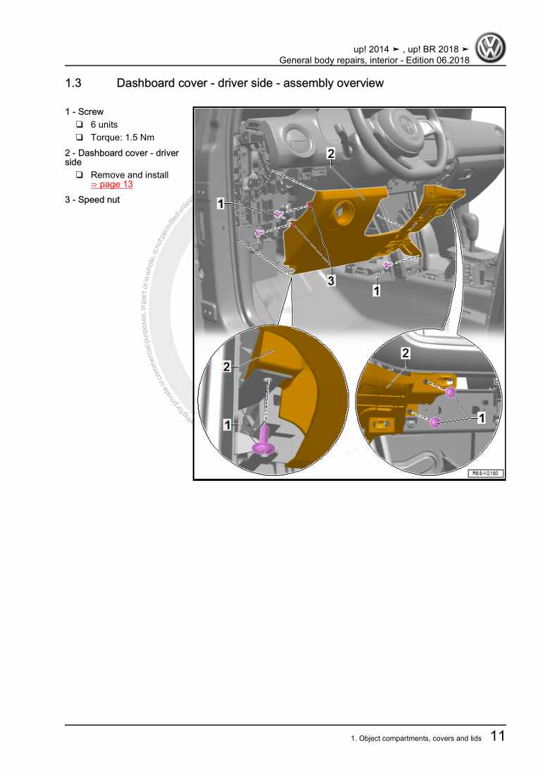
General body repairs, interior

Beispielseite für Reparaturanleitung General body repairs, interior

Für VW UP (Brasilien ) (2014 >) / VW UP (Brasilien) (2014) / VW Up [BR] (2014 >)

15,68 € Details

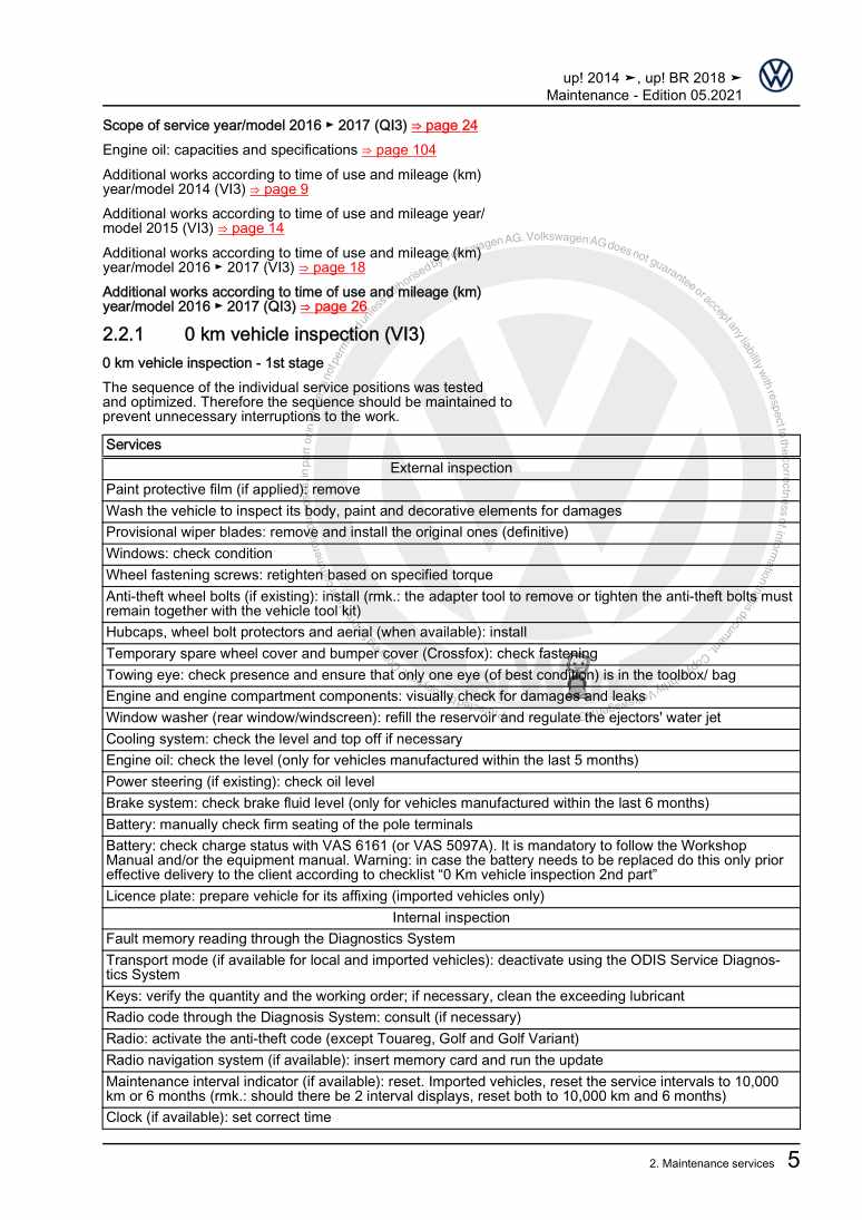
Maintenance

Beispielseite für Reparaturanleitung Maintenance

Für VW UP (Brasilien ) (2014 >) / VW UP (Brasilien) (2014) / VW Up [BR] (2014 >)

13,41 € Details

5 - Speed automated transmission 0CT

Beispielseite für Reparaturanleitung 5 - Speed automated transmission 0CT

Für VW UP (Brasilien ) (2014 >) / VW UP (Brasilien) (2014) / VW Up [BR] (2014 >)

12,18 € Details

Unsere Best Seller

Schon gewusst? Wir bieten auch originale Autoteile an.

Autoteil 5NB857189GHZG Blende

5NB857189GHZG

Blende

314,75 €

Details
Autoteil 4H0035402 Lautsprech

4H0035402

Lautsprech

133,98 €

Details
Autoteil 5Z0941589 Relais

5Z0941589

Relais

39,48 €

Details
Autoteil 7H7067081 Gasdrfeder

7H7067081

Gasdrfeder

35,85 €

Details
Autoteil 0BF598079 Rep.Satz

0BF598079

Rep.Satz

187,48 €

Details

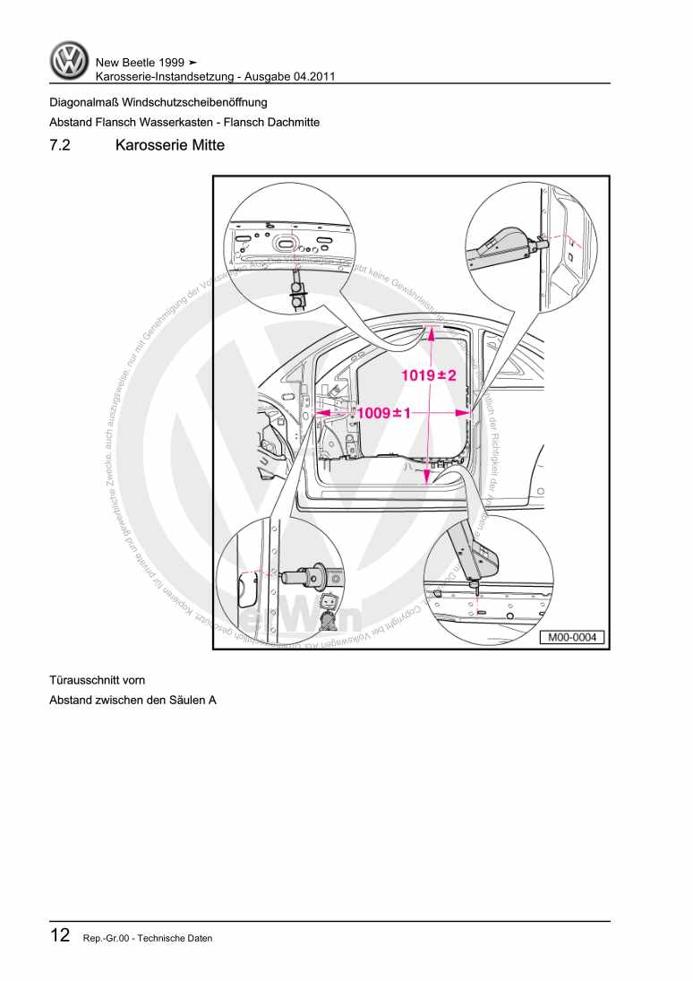
Karosserie-Instandsetzung

Beispielseite für Reparaturanleitung Karosserie-Instandsetzung

Für New Beetle / New Beetle (USA) (1998 - 2007) / New Beetle (Europe) (1999 - 2002)

10,12 € Details

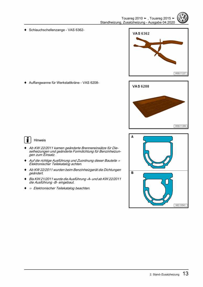
Standheizung, Zusatzheizung

Beispielseite für Reparaturanleitung Standheizung, Zusatzheizung

Für Touareg (2011) / Touareg FL (2015 > )

6,64 € Details

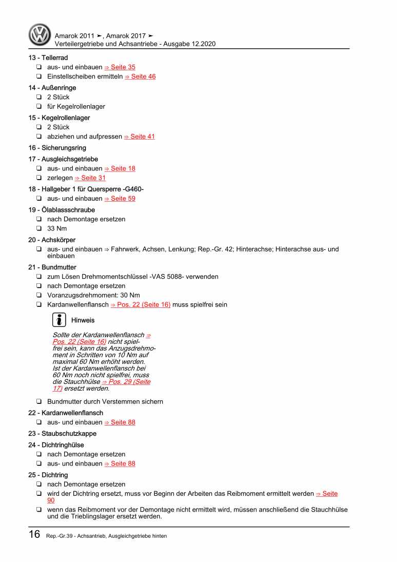
Verteilergetriebe und Achsantriebe

Beispielseite für Reparaturanleitung Verteilergetriebe und Achsantriebe

Für Amarok (2011) / Amarok (2013) / Amarok (2017 >) / Amarok (2017)

16,26 € Details

image/svg+xml Über Clonck

Originale Reparaturanleitungen und Ersatzteile

Unsere Reparaturanleitungen sind Originale, kommen direkt von Volkswagen und erfüllen die höchsten Qualitätsstandards.

In unserem Originalteile-Shop verkaufen wir hochwertige Originalersatzteile der Fahrzeughersteller. Mithilfe der Suche gibst du die gewünschte Teilenummer (OE-Nummer) ein und bestellst schnell und einfach das benötigte Ersatzteil.

Höchste Qualitätsstandards

Bei Clonck wollen wir Autoschrauber und Kfz-Profis glücklich machen. Aus diesem Grund findest du bei Clonck ausschließlich professionelle und hochwertige Reparaturanleitungen, mit deren Hilfe du dein Fahrzeug fachgerecht reparieren kannst.

Unsere Partner

Autohaus Schmidt GmbH
Automag GmbH Filiale Laim
KFZ-VERLAG GmbH
Zimpel und Franke GmbH

Clonck: Der Autoreparatur-Shop - gibt's auch als App!

Clonck App Logo Play Store

Clonck: Passende Autoteile für deine Autoreparatur

4,5 90

Mit Clonck bestellst du die richtigen Originalersatzteile im Handumdrehen.

  • Fahrzeugmodell hinzufügen
  • Baugruppe auswählen
  • Fahrzeug-Identifizierungsnummer (FIN) eingeben
  • Über 5.000 originale Reparaturanleitungen einsehen
Jetzt App starten
Clonck App Preview Auto Mobiltelefon Autoteile