DER AUTOREPARATUR-SHOP
0
Home » Anleitungen » Heating, air conditioner
  • Beispielseite für Reparaturanleitung Heating, air conditioner
  • Beispielseite für Reparaturanleitung 2 Heating, air conditioner
  • Beispielseite für Reparaturanleitung 3 Heating, air conditioner
  • Beispielseite für Reparaturanleitung Heating, air conditioner
  • Beispielseite für Reparaturanleitung 2 Heating, air conditioner
  • Beispielseite für Reparaturanleitung 3 Heating, air conditioner

Heating, air conditioner

Für T-Cross

Original VW-Reparaturanleitung


16,55 €inkl. 7% MwSt.

Sofort als Download verfügbar

Sprache: English

Digitale PDF Version

13.405 KB

199 Seiten

Detaillierte technische Daten

Sofort lesbar

Diese Reparaturanleitung umfasst: Overview of fitting locations - heating, Actuators, Operating and display unit und Air conditioner compressor. Mehr anzeigen
Sichere Zahlung per PayPal, Kreditkarte, Lastschrift, Sofort-Überweisung oder Giropay
PayPal Logo SEPA Lastschrift Logo Giropay Logo Sofort Überweisung Logo

Reparaturanleitung T-Cross Heating, air conditioner pdf Download mit dem Inhalt:

Kapitelübersicht

  • Technical data
    1
  • 1 Safety information
    1
  • 1.1 Safety precautions when working on air conditioning systems
    1
  • 1.2 Safety measures when working on vehicles with a start/stop system
    1
  • 1.4 Safety precautions when working on the cooling system
    2
  • 1.5 Safety precautions when handling refrigerants
    2
  • 1.6 Safety precautions when working on SCR system
    3
  • 2 Identification
    5
  • 2.1 Identification of heater and air conditioning unit
    5
  • 3 General information
    7
  • 3.1 Type plates
    7
  • 3.2 Notes for vehicles with start-stop system
    9
  • 4 Repair instructions
    11
  • 4.1 Rules for cleanliness
    11
  • 4.2 General information
    11
  • 4.3 General repair instructions
    11
  • 4.4 Contact corrosion
    12
  • 4.5 Nuts and bolts
    12
  • 4.6 Routing and attachment of lines
    12
  • 4.7 Fitting radiators and condensers
    12
  • 4.8 Working on refrigerant circuit
    13
  • 4.9 Refrigerant circuit seals
    14
  • 5 Technical data
    15
  • 5.1 Refrigerant capacity
    15
  • 5.2 Refrigerant oil capacities
    15
  • 5.3 Oil distribution
    16
  • Heating
    17
  • 1 Overview of fitting locations - heating
    17
  • 1.1 Overview of fitting locations - components not located in passenger compartment
    17
  • 2 Actuators
    22
  • 2.1 Overview of fitting locations - front actuators
    22
  • 2.2 Removing and installing temperature flap actuator
    24
  • 2.3 Removing and installing air distribution flap actuator
    24
  • 2.4 Removing and installing flexible shaft for air distribution
    24
  • 2.5 Removing and installing flexible shaft for temperature flap
    24
  • 3 Heater
    25
  • 3.1 Assembly overview – heater unit
    25
  • 3.2 Removing and installing fresh air blower V2
    27
  • 3.3 Removing and installing fresh air blower series resistor with overheating fuse N24
    27
  • 3.4 Removing and installing heat exchanger
    27
  • 3.5 Removing and installing heater unit
    28
  • 3.6 Dismantling and assembling heater unit
    28
  • 4 Air duct
    29
  • 5 Operating and display unit
    30
  • 5.1 Overview of operating and display unit
    30
  • 5.2 Removing and installing operating and display unit
    30
  • 6 Other controlling and regulating components
    32
  • Air conditioning system
    33
  • 1 Overview of fitting locations - air conditioning system
    33
  • 1.1 Overview of fitting locations - components not located in passenger compartment
    33
  • 2 Refrigerant circuit
    37
  • 2.1 System overview - refrigerant circuit
    37
  • 2.2 Assembly overview – condenser
    39
  • 2.3 Removing and installing refrigerant circuit pressure sender G805
    41
  • 2.4 Removing and installing expansion valve
    42
  • 2.5 Removing and installing condenser
    46
  • 2.6 Removing and installing desiccant bag or cartridge
    50
  • 2.8 Commissioning air conditioning system after filling refrigerant circuit
    62
  • 3 Air conditioner compressor
    73
  • 3.1 Assembly overview – drive unit of air conditioner compressor
    73
  • 3.2 Assembly overview - pulley
    77
  • 3.3 Removing air conditioning compressor from and installing on bracket
    81
  • 3.4 Removing and installing air conditioner compressor
    83
  • 3.5 Checking high-pressure safety valve on air conditioner compressor
    88
  • 3.6 Removing and installing pulley
    90
  • 4 Control motors
    99
  • 4.1 Overview of fitting locations – control motors at front
    99
  • 4.2 Removing and installing defroster flap control motor V107
    104
  • 4.3 Removing and installing front air distribution flap control motor V426
    107
  • 4.4 Removing and installing fresh air and air recirculation flap control motor V154
    108
  • 4.5 Removing and installing left temperature flap control motor V158
    110
  • 4.6 Removing and installing right temperature flap control motor V159
    113
  • 4.7 Removing and installing fresh air/air recirculation, air flow flap control motor V425
    116
  • 4.8 Removing and installing air distribution flap actuator
    119
  • 4.9 Removing and installing temperature flap actuator
    122
  • 4.10 Removing and installing flexible shaft for temperature flap
    124
  • 4.11 Removing and installing flexible shaft for air distribution
    124
  • 5 Front heater and air conditioning unit
    126
  • 5.1 Assembly overview – heater and air conditioning unit
    126
  • 5.2 Assembly overview – evaporator housing
    128
  • 5.3 Removing and installing evaporator
    130
  • 5.4 Checking auxiliary air heater element Z35
    131
  • 5.5 Removing and installing auxiliary air heater element Z35
    132
  • 5.6 Removing and installing heater and air conditioning unit
    134
  • 5.7 Removing and installing holder for heater and air conditioning unit
    139
  • 5.8 Dismantling and assembling heater and air conditioning unit
    140
  • 5.9 Removing and installing air distribution housing
    140
  • 5.10 Removing and installing dust and pollen filter
    141
  • 5.11 Removing and installing fresh air blower V2
    145
  • 5.12 Removing and installing fresh air blower control unit J126
    146
  • 5.13 Removing and installing heat exchanger
    147
  • 5.14 Removing and installing coolant pipes on heat exchanger
    155
  • 5.15 Removing and installing evaporator temperature sensor G308
    157
  • 5.16 Removing and installing flexible shafts
    159
  • 5.17 Removing and installing condensation drain
    163
  • 5.18 Checking condensation drain
    166
  • 5.19 Removing and installing fresh air blower series resistor with overheating fuse N24
    166
  • 6 Air duct
    168
  • 6.1 Assembly overview – air duct and air distribution in passenger compartment
    168
  • 6.2 Removing and installing driver side footwell vents
    170
  • 6.3 Removing and installing front passenger side footwell vents
    172
  • 6.4 Removing and installing rear footwell vent
    174
  • 6.5 Removing and installing forced ventilation for passenger compartment
    175
  • 6.6 Checking forced ventilation for passenger compartment
    176
  • 6.7 Removing and installing fresh air intake
    177
  • 6.8 Removing and installing cover for fresh air intake
    178
  • 6.9 Removing and installing air intake duct
    178
  • 6.10 Removing and installing air duct for defroster vent
    179
  • 6.11 Removing and installing air duct for centre vent
    180
  • 7 Operating and display unit
    181
  • 7.1 Overview of operating and display unit
    181
  • 7.2 Removing and installing operating and display unit
    184
  • 8 Other controlling and regulating components
    187
  • 8.1 Removing and installing sunlight penetration photosensor G107
    187
  • 8.2 Removing and installing ambient temperature sensor G17
    188
  • 8.3 Removing and installing humidity sender for air conditioning system G260
    188
  • 8.4 Removing and installing left vent temperature sender G150
    189
  • 8.5 Removing and installing right vent temperature sender G151
    190
  • 8.6 Removing and installing footwell vent temperature sender G192
    192
Hersteller­bezeichnung Heating, air conditioner
Hersteller Volkswagen
Passend für T-Cross (2019 >)
Passende Autotypen C11
Kategorie Reparaturanleitung

Im Moment sind noch keine Bewertungen für dieses Produkt vorhanden.

Ähnliche Reparaturanleitungen

Installed 5-speed manual gearbox 0AH

Beispielseite für Reparaturanleitung Installed 5-speed manual gearbox 0AH

Für T-Cross (2019 >)

8,28 € Details

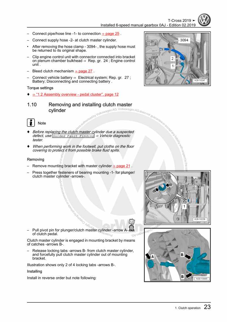
Installed 6-speed manual gearbox 0AJ

Beispielseite für Reparaturanleitung Installed 6-speed manual gearbox 0AJ

Für T-Cross (2019 >)

8,22 € Details

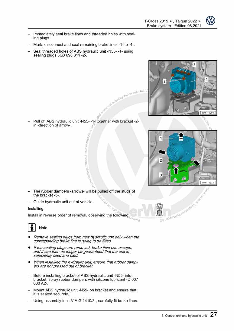
Brake system

Beispielseite für Reparaturanleitung Brake system

Für T-Cross (2019 >)

14,07 € Details

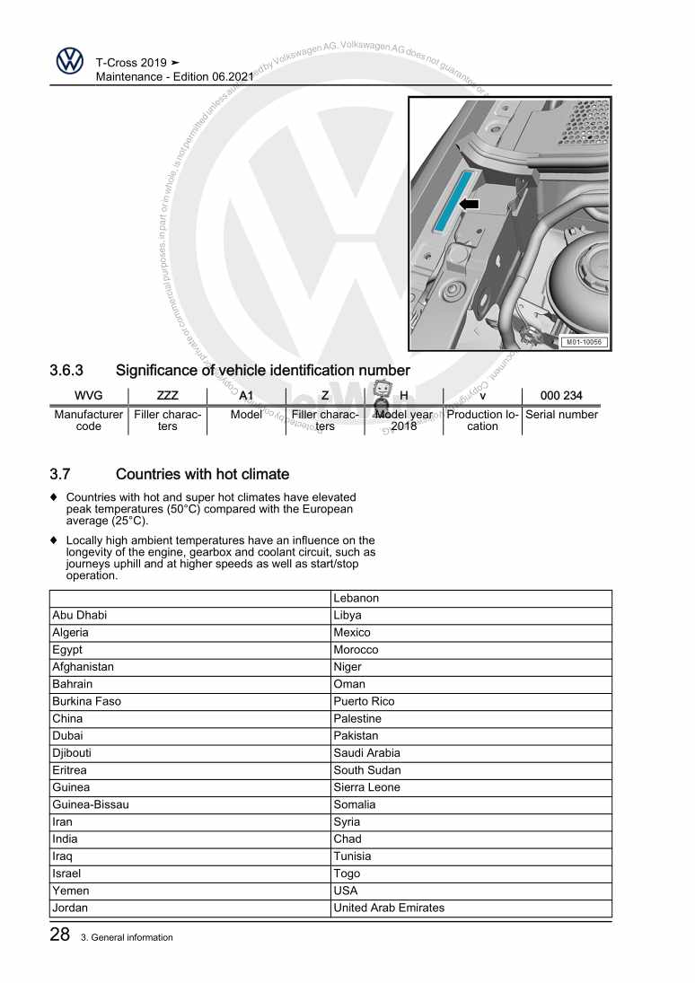
Maintenance

Beispielseite für Reparaturanleitung Maintenance

Für T-Cross (2019 >)

12,98 € Details

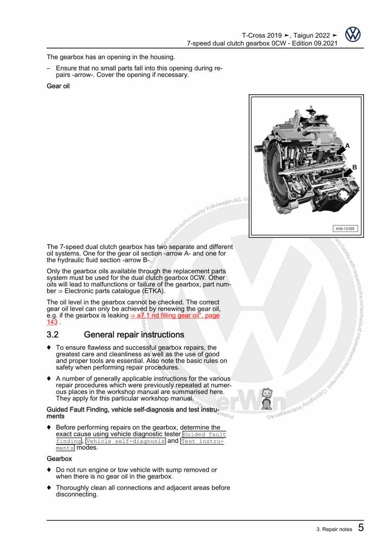
7-speed dual clutch gearbox 0CW

Beispielseite für Reparaturanleitung 7-speed dual clutch gearbox 0CW

Für T-Cross (2019 >)

14,14 € Details

Wheels and Tyres Guide

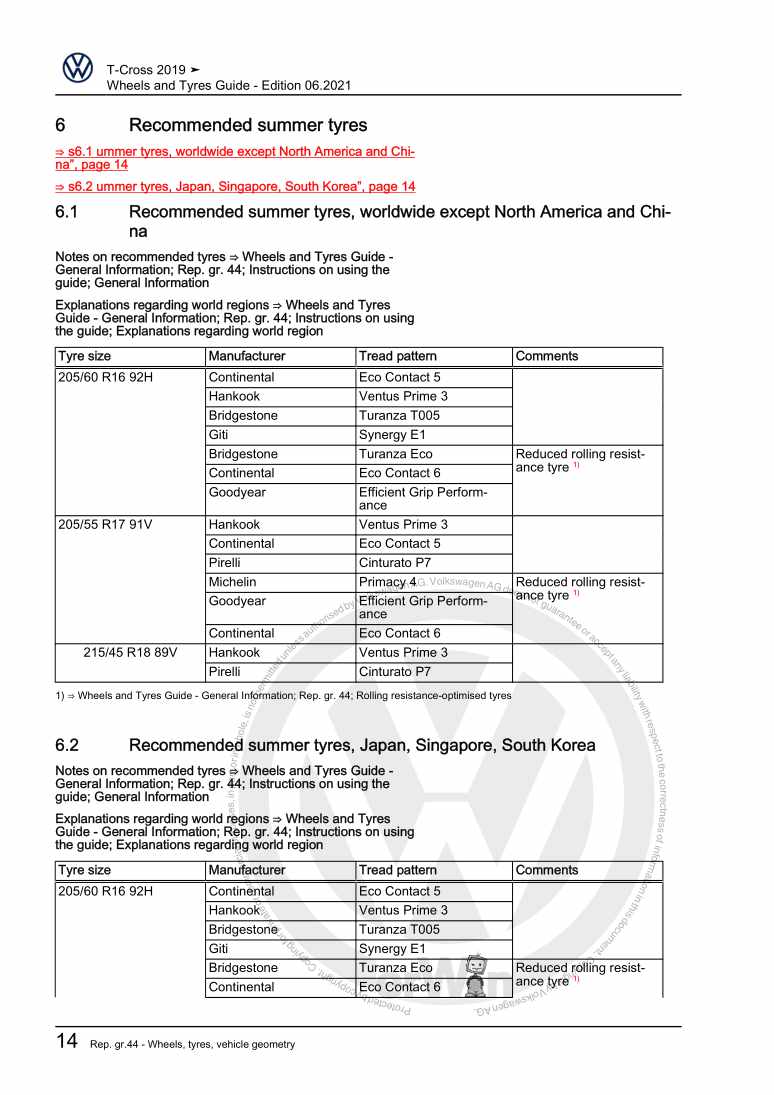
Beispielseite für Reparaturanleitung Wheels and Tyres Guide

Für T-Cross (2019 >)

4,75 € Details

Running gear, axles, steering

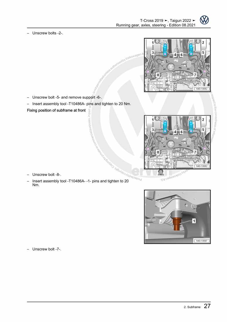
Beispielseite für Reparaturanleitung Running gear, axles, steering

Für T-Cross (2019 >)

15,31 € Details

Installed 5-speed manual gearbox 0DF

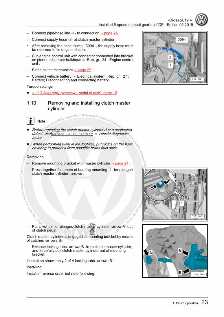
Beispielseite für Reparaturanleitung Installed 5-speed manual gearbox 0DF

Für T-Cross (2019 >)

8,28 € Details

Vehicle-specific paint information

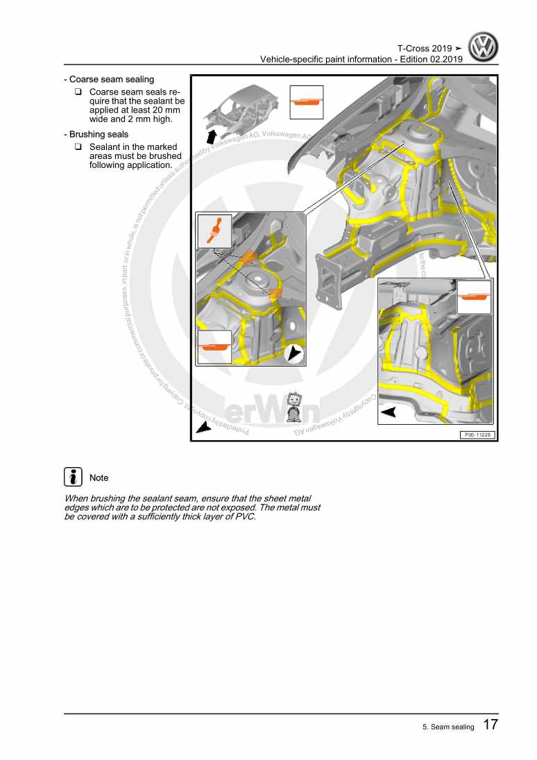
Beispielseite für Reparaturanleitung Vehicle-specific paint information

Für T-Cross (2019 >)

5,78 € Details

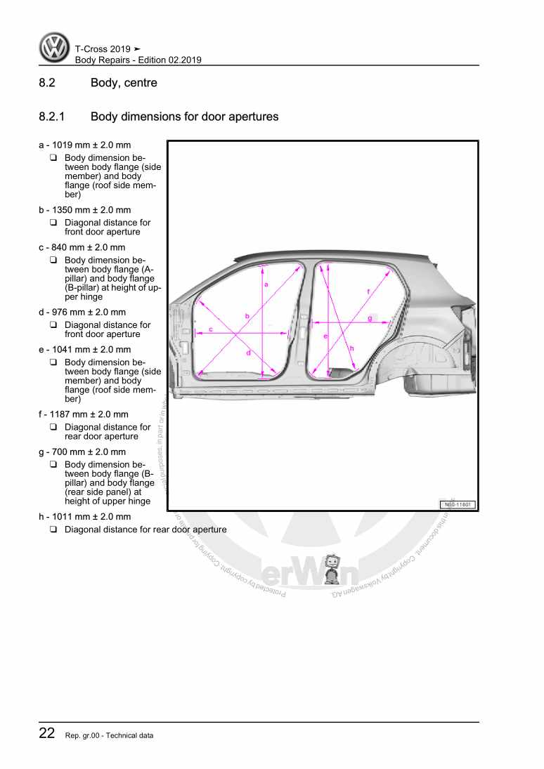
Body Repairs

Beispielseite für Reparaturanleitung Body Repairs

Für T-Cross (2019 >)

24,58 € Details

Unsere Best Seller

Schon gewusst? Wir bieten auch originale Autoteile an.

Autoteil 7E7068025 Drucktaste

7E7068025

Drucktaste

16,63 €

Details
Autoteil 1J1721465BC Leitung

1J1721465BC

Leitung

188,17 €

Details
Autoteil 4G8805607 Aufnahme

4G8805607

Aufnahme

36,47 €

Details
Autoteil ASE44202100000 Adapter

ASE44202100000

Adapter

12,45 €

Details
Autoteil 4H0035402 Lautsprech

4H0035402

Lautsprech

143,01 €

Details

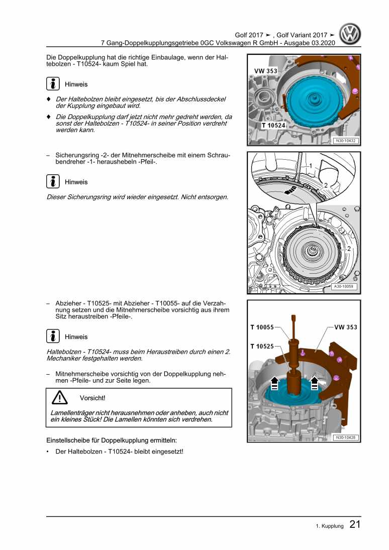
7 Gang-Doppelkupplungsgetriebe 0GC Volkswagen R GmbH

Beispielseite für Reparaturanleitung 7 Gang-Doppelkupplungsgetriebe 0GC Volkswagen R GmbH

Für Golf VII (2017) / Golf (2017)

10,54 € Details

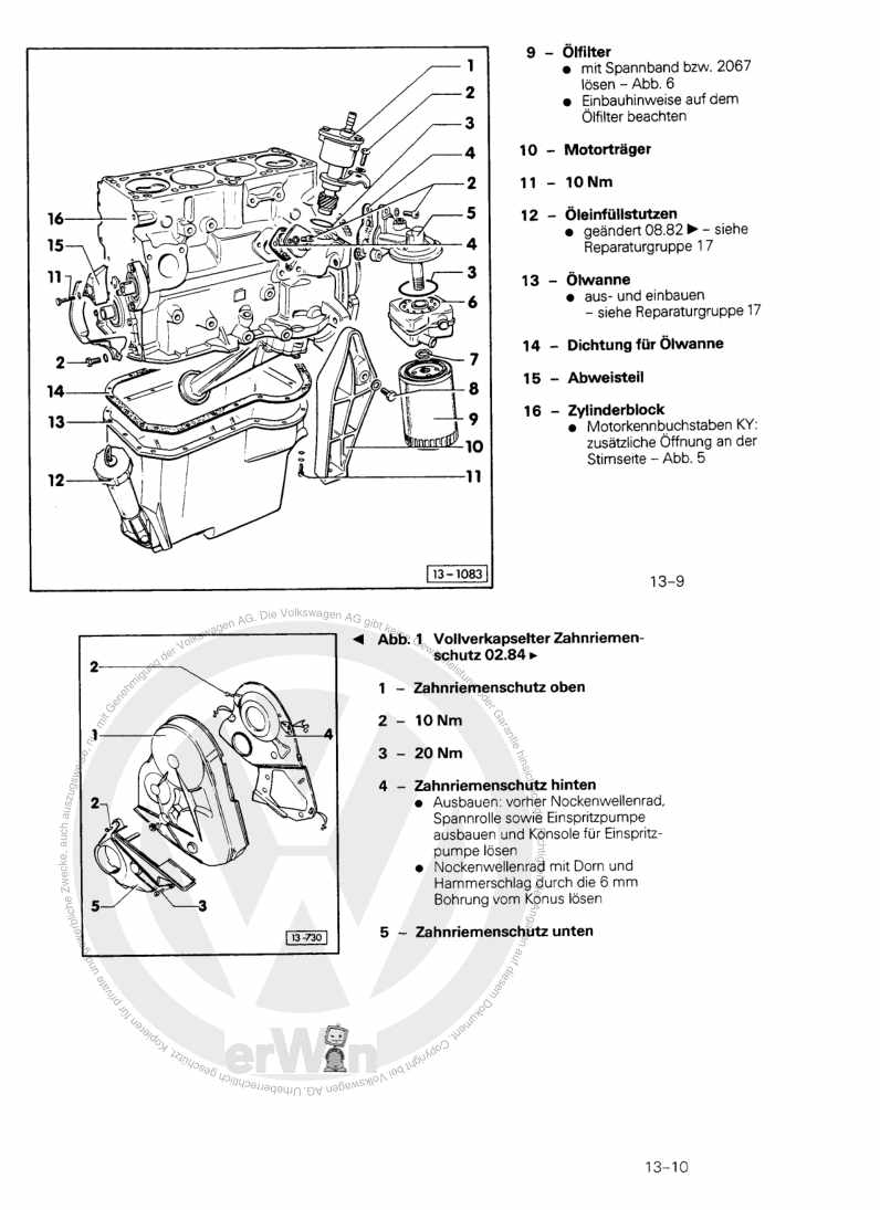
4-Zylinder-Dieselmotor, Mechanik CS,JX,KY

Beispielseite für Reparaturanleitung 4-Zylinder-Dieselmotor, Mechanik CS,JX,KY

Für Typ 2 / Typ 2 7-9-Sitzer / Typ 2 Doppelkabine / Typ 2 Pritsche (1968 - 2007) / MICROBUS / Typ 2 Bus/Caravelle / Typ 2 Kasten / Typ 2 Kombi/... / VAN (1980 - 1999)

8,15 € Details

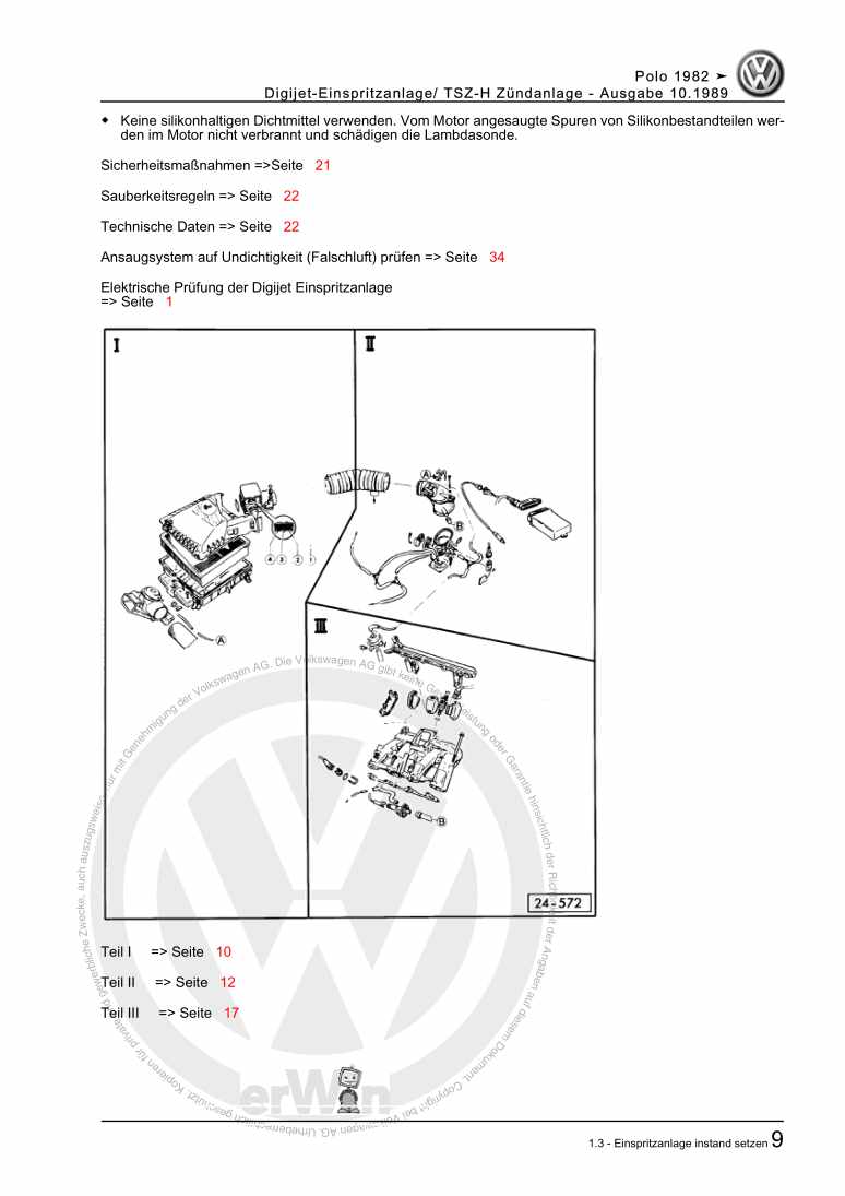
Digijet-Einspritzanlage/ TSZ-H Zündanlage

Beispielseite für Reparaturanleitung Digijet-Einspritzanlage/ TSZ-H Zündanlage

Für Polo / Polo Coupe / Polo Steilheck / Polo Stufenheck (1987 - 1994)

6,35 € Details

image/svg+xml Über Clonck

Originale Reparaturanleitungen und Ersatzteile

Unsere Reparaturanleitungen sind Originale, kommen direkt von Volkswagen und erfüllen die höchsten Qualitätsstandards.

In unserem Originalteile-Shop verkaufen wir hochwertige Originalersatzteile der Fahrzeughersteller. Mithilfe der Suche gibst du die gewünschte Teilenummer (OE-Nummer) ein und bestellst schnell und einfach das benötigte Ersatzteil.

Höchste Qualitätsstandards

Bei Clonck wollen wir Autoschrauber und Kfz-Profis glücklich machen. Aus diesem Grund findest du bei Clonck ausschließlich professionelle und hochwertige Reparaturanleitungen, mit deren Hilfe du dein Fahrzeug fachgerecht reparieren kannst.

Unsere Partner

Autohaus Schmidt GmbH
Automag GmbH Filiale Laim
KFZ-VERLAG GmbH
Zimpel und Franke GmbH

Clonck: Der Autoreparatur-Shop - gibt's auch als App!

Clonck App Logo Play Store

Clonck: Passende Autoteile für deine Autoreparatur

4,5 90

Mit Clonck bestellst du die richtigen Originalersatzteile im Handumdrehen.

  • Fahrzeugmodell hinzufügen
  • Baugruppe auswählen
  • Fahrzeug-Identifizierungsnummer (FIN) eingeben
  • Über 5.000 originale Reparaturanleitungen einsehen
Jetzt App starten
Clonck App Preview Auto Mobiltelefon Autoteile