Starter, current supply, CCS
11 Battery
11.1 Fundamentals for batteries
11.2 Types of battery
11.3 Warning notices and safety regulations
11.4 Battery terminal connection
12 Checking battery
23 Charging battery
34 Disconnecting and reconnecting battery
44.1 Disconnecting and reconnecting batteries, vehicles with two-battery concept
44.2 Disconnecting and reconnecting batteries, vehicles with electric power latching
85 Removing and installing battery
105.1 Removing and installing battery on right in luggage compartment
105.2 Removing and installing battery on left in luggage compartment
126 Battery isolation relay J7
176.1 Removing and installing battery isolation relay J7
177 Pyrotechnic battery isolator
197.1 Overview of fitting locations
197.2 Safety precautions when working on pyrotechnical battery isolator
207.3 Disposal of pyrotechnical battery isolation units
207.4 Removing and installing pyrotechnical battery isolator
208 Removing and installing battery monitor control unit J367
239 Starter, vehicles with automatic gearbox
259.1 Checking starter B
259.2 Starter, vehicles with 3.2 l, 177 kW injection engine, automatic gearbox AL420-6Q
259.3 Starter, vehicles with 3.6 l, 206 kW injection engine, automatic gearbox AL420-6Q
289.4 Starter, vehicles with 4.2 l, 246 kW injection engine, automatic gearbox AL420-6Q
319.6 Starter, vehicles with 3.0 l, 176 kW TDI engine, automatic gearbox AL420-6Q
389.7 Starter, vehicles with 4.9 l, 230 kW TDI engine, automatic gearbox AL750-6A
4010 Alternator
4610.1 Characteristics of alternators
4610.2 Securing B+ (battery positive) wire to alternator
4710.3 Checking poly V-belt
4710.4 Alternator, 3.2 l injection engine
4710.5 Alternator, 3.6 l injection engine
5110.6 Alternator, 4.2 l injection engine
5510.7 Alternator, 6.0 l injection engine
5910.8 Alternator, 3.0 l TDI engine
6210.9 Alternator, 4.9 l TDI engine
6610.10 Removing and installing poly V-belt pulley on alternator
7210.11 Removing and installing poly V-belt pulley with freewheel from alternator, 4.9 l TDI engine
7411 Cruise control system (CCS)
7612 Adaptive cruise control (ACC)
7712.1 Assembly overview - Automatic adaptive cruise control
7712.2 Removing and installing automatic distance control unit
7812.3 Calibrating adaptive cruise control sensor G550
8012.4 Initialising adaptive cruise control
8112.5 Removing and installing brake servo control unit J539
81Gauges, instruments
831 Dash panel insert
831.1 Renewing dash panel insert
831.2 Coding dash panel insert
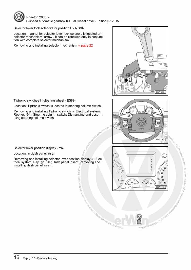
831.3 Removing and installing dash panel insert
831.4 Description of back of dash panel insert
851.5 Pin assignment of connectors on dash panel insert
861.6 Warning lamp symbols in dash panel insert
862 Service interval display
882.1 Resetting service interval display
88Windscreen wash/wipe system
891 Windscreen wiper system
891.1 General description
891.2 Assembly overview - windscreen wiper system
891.3 Removing and installing windscreen wiper system
901.4 Adjusting wiper blade park position
981.5 Removing and installing joint-free wiper blades
991.6 Rain and light sensor G397
1002 Windscreen washer system
1032.1 Assembly overview - windscreen washer system
1032.2 Removing and installing washer fluid reservoir
1042.3 Removing and installing windscreen washer pump V5
1062.4 Removing and installing windscreen washer fluid level sender G33
1072.5 Removing and installing windscreen washer system spray jets
1072.6 Checking spray jets for windscreen washer system
1083 Headlight washer system
1093.1 Assembly overview - headlight washer system
1093.2 Removing and installing headlight washer system pump V11
1113.3 Removing and installing spray jet pop-up cylinders
1113.4 Removing and installing spray jet assembly
1133.5 Checking and adjusting washer jets
1133.6 Bleeding headlight washer system
1144 Washer fluid line hose couplings
1155 Hose repair
116Lights, bulbs, switches - exterior
1171 Operation and safety notes for gas discharge bulbs
1172 Headlight with gas discharge bulb
1202.1 General description
1202.2 Assembly overview, headlights with a gas discharge bulb
1202.3 Removing and installing headlight
1222.4 Adjusting headlight installation position
1242.5 Renewing gas discharge headlight bulb
1262.6 Removing and installing headlight range control motor
1302.7 Removing and installing headlight range control unit
1322.8 Removing and installing vehicle level sender
1332.9 Coding control unit for headlight range control
1332.10 Converting headlights for use when driving on the left or right
1342.11 Adjusting headlights
1373 Headlights with two gas discharge bulbs
1383.1 General description
1383.2 Assembly overview - Headlights with two gas discharge bulbs
1383.3 Removing and installing headlight
1403.4 Adjusting headlight installation position
1423.5 Renewing bulbs in headlights with two gas discharge bulbs
1433.6 Removing and installing headlight range control motor
1483.7 Removing and installing headlight range control unit
1493.8 Removing and installing main beam headlight range control unit
1493.9 Removing and installing vehicle level sender
1503.10 Coding control unit for headlight range control
1513.11 Adjusting headlights
1514.1 General description
1524.3 Removing and installing headlight
1554.4 Adjusting headlight installation position
1584.5 Renewing gas discharge bulbs and cornering light bulbs in headlights
1584.6 Daytime running lights and side light control unit
1634.7 Gas discharge bulb control unit
1634.8 Power output module for headlight
1644.9 Headlight range control unit J431
1664.10 Headlight range control motor
1664.11 Dynamic cornering light control motor
1684.12 Swivel module position sensor
1684.13 Headlight screen adjustment solenoid
1694.14 Removing and installing vehicle level sender
1694.15 LED module for daytime running light and side light
1694.16 Adjusting headlights
1705.1 General description
1715.2 Removing and installing headlight
1715.4 Adjusting headlight installation position
1755.5 Renewing gas discharge bulbs and cornering light bulbs in headlights
1765.6 Daytime running lights and side light control unit
1815.7 Gas discharge bulb control unit
1815.8 Power output module for headlight
1825.9 Headlight range control unit J431
1845.10 Headlight range control motor
1845.11 Dynamic cornering light control motor
1865.12 Swivel module position sensor
1865.13 Headlight screen adjustment solenoid
1875.14 LED module for daytime running light and side light
1875.15 Adjusting headlights
1886.1 General description
1896.2 Assembly overview - headlight
1906.3 Removing and installing headlight
1926.4 Adjusting headlights
1936.5 Adjusting headlight installation position
1936.6 Removing and installing front turn signal bulb M5 / M7
1936.7 Removing and installing headlight range control motor V48 / V49
1946.8 Removing and installing gas discharge bulb L13 / L14
1966.9 Removing and installing LED modules for daytime running light and side light L176 / L177
1976.10 Removing and installing bulbs for static cornering light L148 / L149
1986.11 Removing and installing control unit for daytime running light and side light J860 / J861
1986.12 Removing and installing gas discharge bulb control unit J343 / J344
1996.13 Removing and installing output module for headlight J667 / J668
2006.14 Removing and installing turn signal control unit
2016.15 Removing and installing control unit for cornering light and headlight range control J745
2016.16 Removing and installing headlight screen adjustment solenoid
2026.17 Removing and installing dynamic cornering light control motor V318 / V319
2026.18 Removing and installing swivel module position sensor G474 / G475
2026.19 Removing and installing control motor for VARILIS headlight V446 / V447
2026.20 Removing and installing control motor sender for VARILIS headlight G695 / G696
2027 Fog lights
2037.1 Removing and installing fog light
2037.2 Removing and installing fog light bulb
2047.3 Adjusting fog lights
2048 Front side marker light bulb
2058.1 Removing and installing side marking light bulb
2059 Turn signal repeater bulb and entry light in exterior mirror
2069.1 Removing and installing turn signal repeater
2069.2 Removing and installing entry light in exterior mirror
20610 Tail light cluster with LED
20810.1 Tail light (tail light cluster) with LEDs in side panel
20810.2 Tail light (tail light cluster) in rear lid
21010.3 Tail light (tail light cluster) gaps and shut lines
21310.4 Checking tail light (tail light cluster) function
21411 Number plate light
21611.1 Number plate light X
21611.2 Luminescent number plate
21712 High-level brake lights (additional brake lights)
21912.1 Removing and installing additional brake light
21912.2 Removing and installing bulb carrier
21913 Steering column switch
22113.1 Assembly overview - steering column switch
22113.2 Removing and installing steering column switch
22313.3 Dismantling and assembling steering column switch
22513.4 Pin assignment on steering column switch
22713.5 Coding steering column electronics control unit J527
22814 Entry and start authorisation
23014.1 Emergency release
23014.2 Entry and start authorisation switch E415
23014.3 Entry and start authorisation button E408
23214.4 Entry and start authorisation control unit J518
23414.5 Assembly overview of entry and start authorisation aerials
23614.6 Removing and installing entry and start authorisation aerials
23814.7 Adapting aerial parameters for entry and start authorisation aerials
24115 Parking aid (PDC)
24315.1 General description
24315.2 Assembly overview - parking aid
24315.3 Parking aid control unit J446
24515.4 Front parking aid senders
24615.5 Rear parking aid senders
24715.6 Front parking aid display
24815.7 Rear parking aid display Y15
24915.8 Parking aid warning buzzer
24916 Lane change assist (Side Assist)
25216.1 General description
25216.2 Removing and installing lane change assist control unit with radar sensor
25216.3 Removing and installing lane change assist warning lamps in exterior mirror
25316.4 Calibrating lane change assist
25416.5 Lane change assist control unit final control diagnosis
26116.6 Coding lane change assist control unit
26117 Reverse camera (Rear Assist)
26217.1 General description
26217.2 Assembly overview - reversing camera system
26217.3 Removing and installing reversing camera
26317.4 Reversing camera system control unit J772
26417.5 Calibrating reversing camera system
26518 Front camera for driver assist systems R242
27018.1 General description
27018.2 Removing and installing front camera for driver assist systems R242
27018.3 Calibrating front camera for driver assist systems R242
27118.4 Coding camera control unit J852
27118.5 Removing and installing windscreen heater for lane departure warning
27119 Tyre pressure monitor (TPM) from 2007 onwards
27219.1 Tyre pressure monitor control unit J502
27319.2 Tyre pressure sensors
27419.3 Transmitter units in wheel housing
27419.4 Tyre pressure monitor aerial R207
275Lights, bulbs, switches - interior
2761 Interior lights and switches
2761.1 Rear left footwell light L106 or rear right footwell light L107
2762 Lights and switches in dash panel
2772.1 Light switch E1
2772.2 Switches and instruments illumination regulator E20 and trip recorder zeroing switch E123
2772.3 Rear roller blind switch E149 and parking aid button E266
2782.4 Glove compartment light W6
2792.5 Glove compartment light switch E26
2802.6 Steering column adjustment switch E167
2812.7 Front left footwell lighting bulb L151 or front right footwell light bulb L152
2812.8 Radio controlled clock Y8
2823 Lights and switches in front doors
2873.2 Front right window regulator switch E41
2883.3 Front interior locking buttons for central locking system E308 and E309
2883.4 Door opener lighting L108 and L109
2903.5 Front door contact switch
2913.6 Front left entry light W31 or front right entry light W32
2913.7 Door warning lamps W30 and W36
2924 Lights and switches in rear doors
2944.1 Rear window regulator switches E52 and E54
2944.2 Rear interior locking buttons for central locking system E310 and E311
2944.3 Rear door opener lighting L110 and L111
2964.4 Rear door contact switch
2974.5 Rear entry lights W33 and W34
2974.6 Rear door warning lamps W37 and W38
2985 Lights and switches in luggage compartment
3005.1 Luggage compartment lights W18 and W35
3005.2 Luggage compartment light switch F5
3015.3 Rear lid closing button, in rear lid E406
3016 Lights and switches in roof trim
3036.1 Front interior light W1
3036.2 Front reading lights W19 and W13
3056.3 Sunroof switch E8
3066.4 Rear interior and reading lights
3066.5 Rear interior light buttons E327 and E329
3086.6 Garage door opener
3086.7 Switch unit in roof module
3097 Lights and switches in centre console
3117.2 Key operated switch to deactivate front passenger side airbag E224
3117.3 Starter button E408
3127.6 Switch unit for adjustable rear seat, 4-seater
3147.7 Switch unit for height-adjustment of lumbar support of rear seat, 5-seater
3158 Cigarette lighter
3168.1 Cigarette lighter U1
3169 Horn
3179.1 Treble tone horn H2
3179.2 Bass tone horn H7
318Wiring
3201 Vehicle diagnosis, testing and information systems
3202 Fuse holder
3212.1 Fuse holder under dash panel on left
3212.2 Pre-fuse box in luggage compartment on left
3212.3 Thermal fuse box on driver side
3243 Relay carrier
3263.1 Relay carrier in front right footwell
3264 Electronics boxes
3284.1 E-box on left in luggage compartment
3284.2 E-box on right in plenum chamber
3305 Control units
3335.1 Onboard supply control unit
3335.2 Roof electronics control unit
3356 Wiring harness and connector repairs
336
