Technical data
11 Safety information
11.1 Safety precautions when working on a high-voltage system
11.2 Safety precautions when working in the vicinity of high-voltage components
21.3 Safety regulations for working on fuel supply
21.5 Safety precautions when working on ignition system
31.6 Safety precautions when working on the cooling system
32 Identification
42.1 Engine number/engine data
43 Repair notes
63.1 Rules for cleanliness
63.2 Foreign objects in engine
63.3 Contact corrosion
63.4 Pipe/wire routing and attachment
73.5 Fitting radiator and condensers
73.6 Checking vacuum system
74 Classification of dangers of the high-voltage system
8Removing and installing engine
151 Removing and installing engine
151.1 Removing engine
151.2 Separating engine and gearbox
251.3 Securing engine on engine and gearbox support
271.4 Installing engine
292 Assembly mounting
342.1 Assembly overview - assembly mountings
342.2 Supporting engine in installation position
352.3 Removing and installing motor mounting
392.4 Removing and installing gearbox mounting
432.5 Removing and installing pendulum support
432.6 Checking adjustment of assembly mountings (engine and gearbox mountings)
442.7 Adjusting assembly mountings
453 Motor cover
473.1 Removing and installing engine cover
47Crankshaft group
481 Cylinder block (pulley end)
481.1 Assembly overview - sealing flange, vibration damper
481.2 Removing and installing engine support
491.3 Removing and installing vibration damper
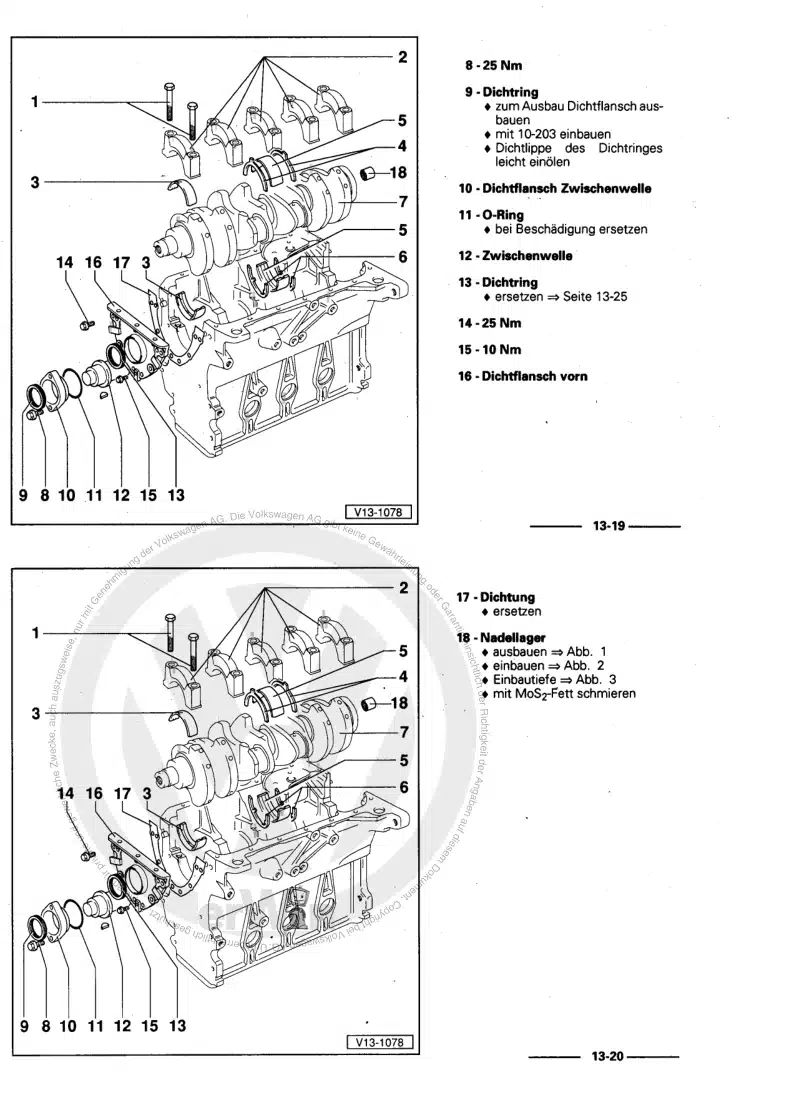
501.4 Renewing crankshaft oil seal - belt pulley end
511.5 Removing and installing sealing flange on pulley end
532 Cylinder block, gearbox end
562.1 Assembly overview - cylinder block, gearbox end
562.2 Removing and installing flywheel
572.3 Removing and installing sealing flange on gearbox side
583 Camshaft
683.1 Crankshaft dimensions
683.2 Measuring axial clearance of crankshaft
683.3 Renewing needle bearing in crankshaft
694 Pistons and conrods
724.1 Assembly overview - pistons and conrods
724.2 Removing and installing pistons
744.3 Removing and installing oil spray jets
754.4 Checking pistons and cylinder bores
764.5 Checking radial clearance of conrods
77Cylinder head, valve gear
791 Cylinder head
791.1 Assembly overview - cylinder head
791.2 Assembly overview - camshaft housing
811.3 Removing and installing cylinder head
821.4 Removing and installing camshaft housing
861.5 Checking compression
952 Toothed belt drive
972.1 Assembly overview - toothed belt cover
972.2 Assembly overview - toothed belt
982.3 Removing toothed belt from camshaft
1002.4 Removing and installing toothed belt
1123 Valve gear
1273.1 Assembly overview - valve gear
1273.2 Removing and installing inlet camshaft control valve 1 N205
1283.3 Measuring axial play of camshaft
1283.4 Removing and installing camshaft oil seal
1293.5 Removing and installing valve stem seals
1344 Inlet and exhaust valves
1424.1 Checking valve guides
1424.2 Checking valves
1424.3 Valve dimensions
143Lubrication
1441 Sump, oil pump
1441.1 Assembly overview - sump/oil pump
1441.2 Engine oil:
1481.3 Removing and installing lower part of sump
1491.4 Removing and installing upper part of sump
1531.5 Removing and installing oil pump
1561.6 Removing and installing oil level and oil temperature sender G266
1572 Engine oil cooler
1592.1 Assembly overview - engine oil cooler
1592.2 Removing and installing engine oil cooler
1593 Crankcase ventilation
1613.1 Assembly overview - crankcase breather system
1613.2 Removing and installing oil separator
1624 Oil filter, oil pressure switch
1644.1 Assembly overview - oil filter/oil pressure switch
1644.2 Removing and installing oil pressure switch F22
1654.3 Removing and installing oil pressure switch for reduced oil pressure F378
1664.4 Removing and installing oil pressure regulating valve N428
1684.5 Checking oil pressure
169Cooling
1711 Cooling system/coolant
1711.1 Connection diagram - coolant hoses
1711.2 Coolant hose schematic diagram, high-voltage system
1731.3 Checking cooling system for leaks
1741.4 Checking cooling system of high-voltage system for leaks
1761.5 Draining and adding coolant
1851.6 Draining and adding coolant, high-voltage system
1911.7 Checking filling quality of cooling system, high-voltage system
1982 Coolant pump, regulation of cooling system
2012.1 Assembly overview - coolant pump, thermostat
2012.2 Assembly overview - electric coolant pump
2042.3 Assembly overview - coolant temperature sender
2052.4 Removing and installing electric coolant pump
2052.5 Removing and installing coolant pump
2112.6 Removing and installing thermostat
2142.7 Removing and installing toothed belt pulley for coolant pump
2182.8 Removing and installing coolant temperature sender G62
2192.9 Removing and installing radiator outlet coolant temperature sender G83
2202.10 Removing and installing coolant valves
2212.11 Removing and installing coolant temperature sender for heater G241
2272.12 Removing and installing engine temperature sender 2 G652
2282.13 Overview of fitting locations - electric coolant pumps
2292.14 Assembly overview - coolant valves
2313 Coolant pipes
2323.1 Assembly overview - coolant pipes
2323.2 Removing and installing coolant pipes
2324 Radiator, radiator fan
2384.1 Assembly overview - radiator, radiator fan
2384.2 Assembly overview - radiator cowl and radiator fan
2404.3 Removing and installing radiator
2404.4 Removing and installing radiator cowling
2444.5 Removing and installing radiator fan V7
245Turbocharging/supercharging
2471 Exhaust turbocharger
2471.1 Assembly overview - turbocharger
2471.2 Removing and installing turbocharger
2481.3 Removing and installing charge pressure positioner V465
2552 Charge air system
2562.1 Assembly overview - charge air system
2562.2 Assembly overview - charge-air hose connections
2572.3 Removing and installing charge pressure sender GX26
2582.4 Removing and installing charge air cooler
2582.5 Checking charge air system for leaks
259Mixture preparation - injection
2611 Injection system
2611.1 Overview of fitting locations - injection system
2611.2 Releasing high pressure in fuel system
2662 Injectors
2682.1 Assembly overview - fuel rail with injectors
2682.2 Removing and installing fuel rail
2692.3 Removing and installing injectors
2692.4 Cleaning injectors
2753 Air filter
2763.1 Assembly overview - air filter housing
2763.2 Removing and installing air filter housing
2774 Intake manifold
2784.1 Assembly overview - intake manifold
2784.2 Removing and installing intake manifold
2794.3 Removing and installing throttle valve module GX3
2824.4 Cleaning throttle valve module GX3
2845 Senders and sensors
2865.1 Removing and installing intake manifold sender GX9
2865.2 Removing and installing fuel pressure sender G247
2865.3 Checking fuel pressure sender G247
2876 Engine (motor) control unit
2906.1 Removing and installing engine (motor) control unit J623
2907 High-pressure pump
2947.1 Assembly overview - high-pressure pump
2947.2 Removing and installing high-pressure pump
2957.3 Removing and installing high-pressure pipe
2968 Lambda probe
2988.1 Assembly overview - Lambda probe
298Exhaust system
3011 Exhaust pipes, silencers
3011.1 Assembly overview - silencers
3011.2 Removing and installing silencer
3011.3 Aligning exhaust system free of stress
3021.4 Check exhaust system for leaks
3022 Exhaust gas cleaning
3032.1 Assembly overview - emission control
3032.2 Removing and installing catalytic converter
304Ignition system
3081 Ignition system
3081.1 Assembly overview - ignition system
3081.2 Test data, spark plugs
3091.3 Removing and installing ignition coils with output stage
3091.4 Removing and installing knock sensor 1 G61
3111.5 Removing and installing Hall sender G40
3121.6 Removing and installing engine speed sender G28
314Electric drive systems
3161 Warning stickers
3161.1 Checking warning stickers
3162 High-voltage components
3212.1 Overview of fitting locations - high-voltage components
3212.2 Testing high-voltage components and high-voltage cables
3223 High-voltage battery unit
3233.1 Assembly overview - high-voltage battery
3233.2 Visual inspection of high-voltage battery 1 AX2
3243.3 Removing and installing high-voltage battery 1 AX2
3243.4 Raising high-voltage battery 1 AX2
3303.5 Removing and installing battery regulation control unit J840
3314 Power and control electronics for electric drive
3334.1 Assembly overview - power and control electronics for electric drive
3334.3 Removing and installing power and control electronics for electric drive
3364.4 Removing and installing bracket for power and control electronics for electric drive JX1
3404.5 Removing and installing high-voltage system fuse 3 S353
3415 Charging unit for high-voltage battery
3445.1 Assembly overview - charging unit for high-voltage battery
3445.2 Removing and installing charging unit 1 for high-voltage battery AX4
3456 Electric drive motor
3496.1 Removing and installing three-phase current drive VX54
3496.2 Removing and installing drive motor temperature sender G712
3496.3 Removing and installing drive motor rotor position sender 1 G713
3497 High-voltage cables
3507.1 Overview of fitting locations - high-voltage cables
3507.2 Removing and installing high-voltage wiring harness for high-voltage battery
3537.3 Removing and installing high-voltage wiring harness for drive motor
3577.5 Removing and installing high-voltage cable for high-voltage heater (PTC)
3618 Charging socket
3648.1 Assembly overview - charging socket
3648.2 Removing and installing high-voltage battery charging socket 1 UX4
3658.3 Emergency release charging connector
3668.4 Removing and installing button and display module
3689 De-energising high-voltage system
36910 Re-energising high-voltage system
37111 Potential equalisation lines
37211.1 General notes - potential equalisation lines
37211.2 Overview of fitting locations - potential equalisation lines
37211.3 Removing and installing potential equalisation line for high-voltage battery 1 AX2
375