Technical data
11 Identification
11.1 Engine number/engine data
12 General information
32.1 Numbering of cylinders
33 Safety information
43.1 Safety regulations for working on fuel supply
43.3 Safety precautions when working on cooling system
63.4 Safety precautions when working on ignition system
73.5 Releasing high pressure in fuel system
74 Repair instructions
114.1 Rules for cleanliness
114.2 Foreign objects in engine
114.3 Contact corrosion
114.4 Routing and attachment of lines
124.5 Fitting radiator and condensers
12Removing and installing engine
131 Removing and installing engine
131.1 Removing engine
131.2 Separating engine and gearbox
241.3 Securing engine on engine and gearbox support
251.4 Installing engine
272 Assembly mountings
302.1 Assembly overview - assembly mountings
302.2 Removing and installing engine mounting
322.3 Supporting engine in installation position
382.4 Adjusting assembly mountings
442.5 Checking adjustment of assembly mountings
463 Engine cover panel
473.1 Removing and installing engine cover
47Crankshaft group
481 Cylinder block (pulley end)
481.1 Assembly overview - poly V-belt drive
481.2 Removing and installing poly-V belt
511.3 Removing and installing tensioner for poly V-belt
531.4 Removing and installing vibration damper
591.5 Removing and installing bracket for ancillaries
661.6 Renewing crankshaft oil seal - belt pulley end
692 Cylinder block, gearbox end
722.1 Assembly overview - cylinder block, gearbox end
722.2 Removing and installing flywheel
742.3 Removing and installing drive plate
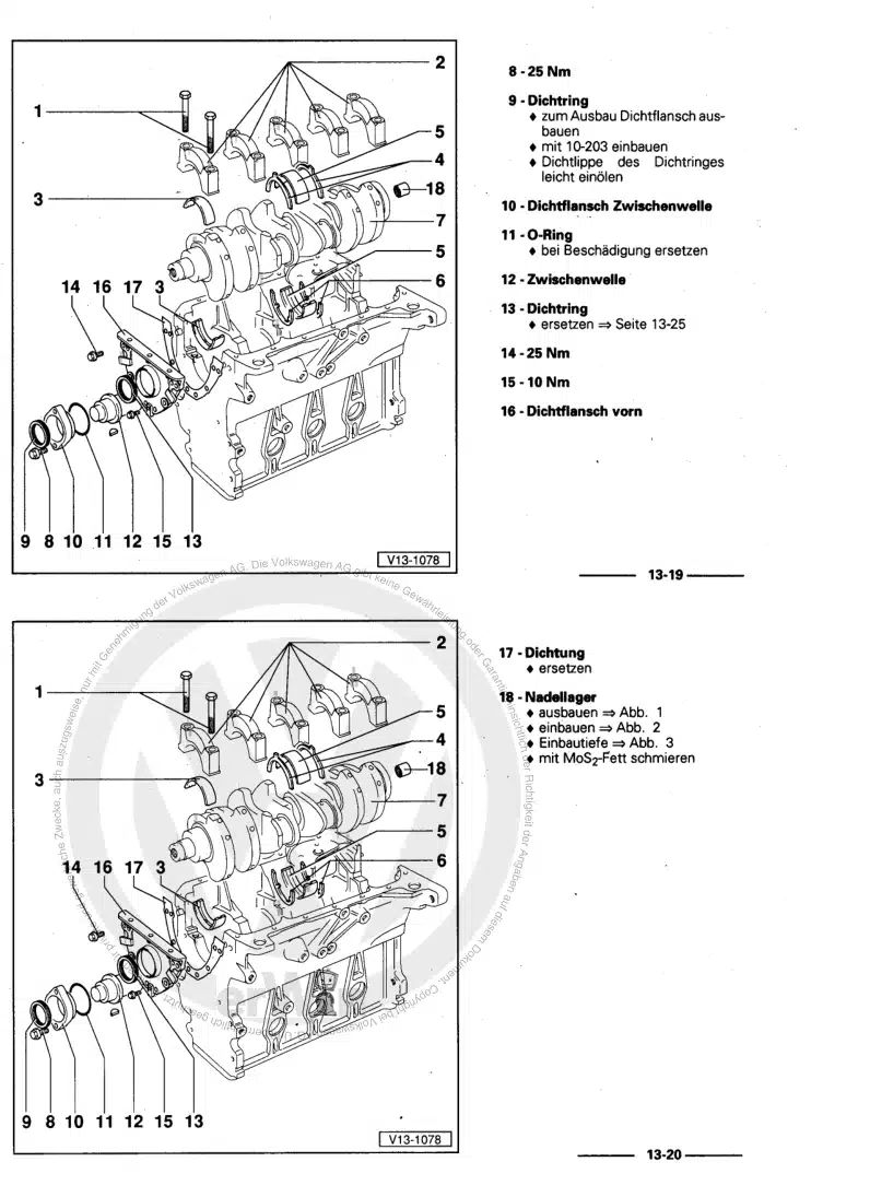
762.4 Removing and installing sealing flange on gearbox side
793 Crankshaft
873.1 Assembly overview - crankshaft
873.2 Renewing needle bearing in crankshaft
893.3 Crankshaft dimensions
913.4 Measuring axial clearance of crankshaft
923.5 Measuring radial clearance of crankshaft
933.6 Allocation of main bearing shells
933.7 Removing and installing sender wheel
954 Balancer shaft
974.1 Removing and installing balance shaft
975 Pistons and conrods
1055.1 Assembly overview - pistons and conrods
1055.2 Checking pistons and cylinder bores
1075.3 Separating new conrod
109Cylinder head, valve gear
1111 Cylinder head
1111.1 Assembly overview - cylinder head
1111.2 Removing and installing cylinder head
1151.3 Removing and installing vacuum pump
1361.4 Checking compression
1382 Cover for timing chain
1402.1 Assembly overview - cover for timing chain
1402.2 Removing and installing timing chain cover
1423 Chain drive
1543.1 Assembly overview - camshaft timing chains
1543.2 Assembly overview - drive chain for balance shaft
1563.3 Removing and installing camshaft timing chain
1593.4 Removing and installing drive chain for balance shaft
1703.5 Checking valve timing
1744 Valve gear
1774.1 Assembly overview - valve gear
1774.2 Measuring axial play of camshaft
1794.3 Removing and installing camshaft
1804.4 Removing and installing valve stem oil seals
1904.5 Removing and installing camshaft control valve 1 N205
1965 Inlet and exhaust valves
1985.1 Checking valve guides
1985.2 Valve dimensions
199Lubrication
2001 Sump, oil pump
2001.1 Assembly overview - sump/oil pump
2001.2 Removing and installing lower part of sump
2031.3 Removing and installing upper part of sump
2061.4 Removing and installing oil pump
2131.5 Engine oil:
2152 Engine oil cooler
2172.1 Removing and installing engine oil cooler
2173 Crankcase ventilation
2213.1 Removing and installing oil separator
2214 Oil filter, oil pressure switch
2234.1 Checking oil pressure and oil pressure switch
2234.2 Assembly overview - oil filter housing, oil pressure switch
2294.3 Removing and installing oil pressure switch F22
2324.4 Removing and installing oil pressure switch for reduced oil pressure F378
2334.5 Removing and installing oil pressure regulating valve N428
234Cooling
2351 Cooling system/coolant
2351.1 Connection diagram - coolant hoses
2351.2 Checking cooling system for leaks
2371.3 Draining and adding coolant
2402 Coolant pump, regulation of cooling system
2462.1 Assembly overview - coolant pump, thermostat
2462.2 Assembly overview - electric coolant pump
2492.3 Removing and installing coolant pump with thermostat housing
2502.5 Removing and installing thermostat
2562.6 Removing and installing toothed belt for coolant pump
2602.7 Renewing seal for coolant pump drive
2632.8 Removing and installing electric coolant pump
2652.9 Removing and installing coolant temperature sender
2663 Coolant pipes
2703.1 Assembly overview - coolant pipes
2703.2 Removing and installing coolant pipes
2714 Radiator, radiator fan
2784.1 Assembly overview - radiator/radiator fan
2784.2 Removing and installing radiator
2794.3 Removing and installing radiator cowl
2814.4 Removing and installing radiator fan
283Turbocharging/supercharging
2841 Turbocharger
2841.1 Assembly overview - turbocharger
2841.2 Removing and installing turbocharger
2911.3 Checking vacuum unit for turbocharger
2991.4 Renewing vacuum unit for turbocharger
3012 Charge air system
3022.1 Schematic overview - charge air system
3022.2 Assembly overview - charge air system
3032.3 Checking charge air system for leaks
3042.4 Assembly overview - charge-air hose connections
306Mixture preparation - injection
3081 Injection system
3081.1 Overview of fitting locations - injection system
3082 Injectors
3152.1 Assembly overview - fuel rail with injectors
3152.2 Removing and installing injectors
3172.3 Renewing seals on injectors
3212.4 Cleaning injectors
3243 High-pressure pump
3263.1 Assembly overview - high-pressure pump
3263.2 Removing and installing high-pressure pump
3284 Senders and sensors
3314.2 Removing and installing air mass meter
3334.3 Removing and installing fuel pressure sender G247
3354.4 Checking fuel pressure sender G247
3375 Intake manifold
3415.1 Assembly overview – intake manifold
3415.2 Removing and installing intake manifold with fuel rail
3445.3 Removing and installing throttle valve module
3525.4 Cleaning throttle valve module
3545.5 Checking intake manifold change-over
3556 Air filter
3586.1 Assembly overview - air filter housing
3586.2 Removing and installing air filter housing
3607 Engine control unit
3627.1 Removing and installing engine control unit J623
362Exhaust system
3651 Exhaust pipes and silencers
3651.1 Assembly overview – silencers
3651.2 Removing and installing front exhaust pipe
3711.3 Separating exhaust pipes from silencers
3741.4 Aligning exhaust system free of stress
3761.5 Checking exhaust system for leaks
3782 Secondary air system
3802.1 Assembly overview - secondary air system
3802.2 Removing and installing secondary air pump motor V101
3802.3 Removing and installing secondary air inlet valve N112
3813 Exhaust manifold
384Ignition system
3851 Ignition system
3851.1 Assembly overview - ignition system
3851.2 Removing and installing ignition coils with output stage
3871.3 Removing and installing knock sensor
3891.4 Removing and installing engine speed sender G28
3901.5 Test data, spark plugs
391