DER AUTOREPARATUR-SHOP
0
Home » Anleitungen » 4-cylinder injection engine (1.6 l engine, 4 valves, MPI)
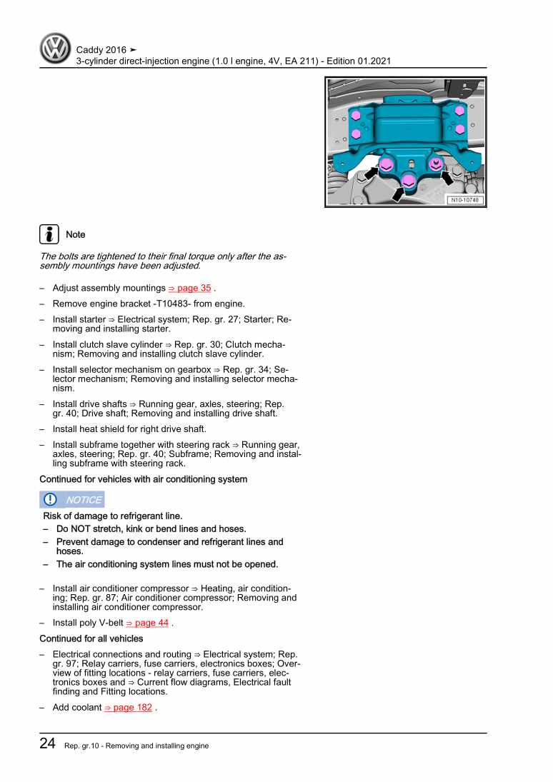
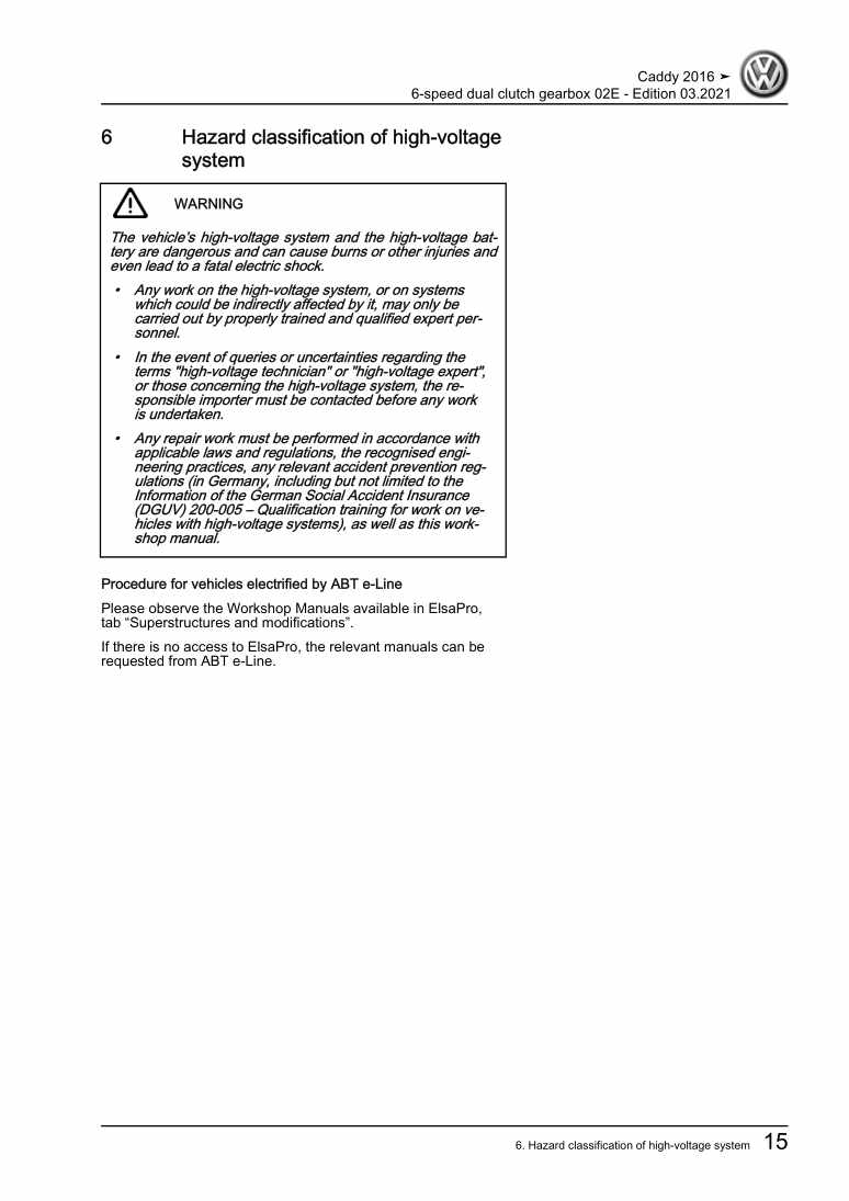
  • Beispielseite für Reparaturanleitung 4-cylinder injection engine (1.6 l engine, 4 valves, MPI)
  • Beispielseite für Reparaturanleitung 2 4-cylinder injection engine (1.6 l engine, 4 valves, MPI)
  • Beispielseite für Reparaturanleitung 3 4-cylinder injection engine (1.6 l engine, 4 valves, MPI)

4-cylinder injection engine (1.6 l engine, 4 valves, MPI)

Für Caddy

Original VW-Reparaturanleitung


19,73 €inkl. 7% MwSt.

  • Deutsch
  • English

Sofort als Download verfügbar

Sprache: English

Digitale PDF Version

29.335 KB

243 Seiten

Detaillierte technische Daten

Sofort lesbar

Diese Reparaturanleitung umfasst: Removing and installing engine, Assembly mountings, Cylinder block (pulley end), Crankshaft, Pistons and conrods, Toothed belt drive, Valve gear, Sump, oil pump, Engine oil cooler, Oil filter, oil pressure switch, Cooling system/coolant, Radiator, radiator fan und Lambda probe. Mehr anzeigen
Sichere Zahlung per PayPal, Kreditkarte, Lastschrift, Sofort-Überweisung oder Giropay
PayPal Logo SEPA Lastschrift Logo Giropay Logo Sofort Überweisung Logo

Reparaturanleitung Caddy 4-cylinder injection engine pdf Download mit dem Inhalt:

Kapitelübersicht

  • Technical data
    1
  • 1 Safety information
    1
  • 1.1 Safety regulations for working on fuel supply
    1
  • 1.2 Safety measures when working on vehicles with a start/stop system
    2
  • 1.4 Safety precautions when working on the cooling system
    2
  • 1.5 Safety precautions when working on ignition system
    2
  • 1.6 Safety precautions when working on exhaust system
    3
  • 2 Identification
    4
  • 2.1 Engine number/engine data
    4
  • 3 Repair instructions
    5
  • 3.1 Rules for cleanliness
    5
  • 3.2 General information
    5
  • 3.3 Foreign objects in engine
    6
  • 3.4 Contact corrosion
    6
  • 3.5 Routing and attachment of lines
    6
  • 3.6 Fitting radiator and condensers
    6
  • 3.7 Checking vacuum system
    7
  • Removing and installing engine
    8
  • 1 Removing and installing engine
    8
  • 1.1 Removing engine
    8
  • 1.2 Separating engine and gearbox
    16
  • 1.3 Securing engine on engine and gearbox support
    20
  • 1.4 Installing engine
    21
  • 2 Assembly mountings
    27
  • 2.1 Assembly overview - assembly mountings
    27
  • 2.2 Removing and installing engine mounting
    28
  • 2.3 Removing and installing gearbox mounting
    30
  • 2.4 Removing and installing pendulum support
    31
  • 2.5 Supporting engine in installation position
    32
  • 2.6 Adjusting assembly mountings
    34
  • 2.7 Checking adjustment of assembly mountings (engine and gearbox mountings)
    36
  • Crankshaft group
    37
  • 1 Cylinder block (pulley end)
    37
  • 1.1 Assembly overview - poly V-belt drive
    37
  • 1.2 Assembly overview - sealing flange, belt pulley end
    41
  • 1.3 Removing and installing poly-V belt
    42
  • 1.4 Removing and installing tensioner for poly V-belt
    45
  • 1.5 Removing and installing vibration damper
    45
  • 1.6 Removing and installing engine support
    46
  • 1.7 Renewing crankshaft oil seal - belt pulley end
    49
  • 1.8 Removing and installing sealing flange on pulley end
    51
  • 2 Cylinder block, gearbox end
    54
  • 2.1 Assembly overview - cylinder block, gearbox end
    54
  • 2.2 Removing and installing flywheel
    55
  • 2.3 Removing and installing sealing flange on gearbox side
    56
  • 3 Crankshaft
    64
  • 3.1 Crankshaft dimensions
    64
  • 3.2 Renewing needle bearing in crankshaft
    64
  • 3.3 Measuring axial clearance of crankshaft
    66
  • 4 Pistons and conrods
    68
  • 4.1 Assembly overview - pistons and conrods
    68
  • 4.2 Removing and installing pistons
    70
  • 4.3 Checking pistons and cylinder bores
    71
  • 4.4 Separating new conrod
    72
  • 4.5 Checking radial clearance of conrods
    73
  • 4.6 Removing and installing oil spray jets
    73
  • Cylinder head, valve gear
    75
  • 1 Cylinder head
    75
  • 1.1 Assembly overview - cylinder head
    75
  • 1.2 Assembly overview - camshaft housing
    77
  • 1.3 Removing and installing cylinder head
    78
  • 1.4 Removing and installing camshaft housing
    82
  • 1.5 Checking compression
    84
  • 2 Toothed belt drive
    87
  • 2.1 Assembly overview - toothed belt cover
    87
  • 2.2 Assembly overview - toothed belt
    88
  • 2.3 Checking valve timing
    89
  • 2.4 Removing toothed belt from camshaft
    94
  • 2.5 Removing and installing toothed belt
    108
  • 3 Valve gear
    124
  • 3.1 Assembly overview - valve gear
    124
  • 3.2 Removing and installing camshaft adjuster
    125
  • 3.3 Measuring axial play of camshaft
    126
  • 3.4 Removing and installing camshaft oil seal
    127
  • 3.5 Removing and installing camshaft control valve 1 N205
    132
  • 3.6 Removing and installing valve stem seals
    133
  • 4 Inlet and exhaust valves
    142
  • 4.1 Checking valve guides
    142
  • 4.2 Checking valves
    142
  • 4.3 Valve dimensions
    143
  • Lubrication
    144
  • 1 Sump, oil pump
    144
  • 1.1 Assembly overview - sump/oil pump
    144
  • 1.2 Engine oil:
    146
  • 1.3 Removing and installing lower part of sump
    146
  • 1.4 Removing and installing upper part of sump
    149
  • 1.5 Removing and installing oil pump
    152
  • 2 Engine oil cooler
    155
  • 2.1 Assembly overview - engine oil cooler
    155
  • 2.2 Removing and installing engine oil cooler
    155
  • 3 Crankcase ventilation
    157
  • 3.1 Assembly overview - crankcase breather system
    157
  • 3.2 Removing and installing oil separator
    158
  • 4 Oil filter, oil pressure switch
    160
  • 4.1 Assembly overview - oil filter/oil pressure switch
    160
  • 4.2 Removing and installing oil pressure switch F1
    160
  • 4.3 Checking oil pressure
    161
  • Cooling
    164
  • 1 Cooling system/coolant
    164
  • 1.1 Connection diagram - coolant hoses
    164
  • 1.2 Draining and adding coolant
    165
  • 1.3 Checking cooling system for leaks
    170
  • 2 Coolant pump, regulation of cooling system
    173
  • 2.1 Assembly overview - coolant pump, thermostat
    173
  • 2.2 Assembly overview - coolant temperature sender
    175
  • 2.3 Removing and installing coolant pump
    177
  • 2.4 Removing and installing toothed belt pulley for coolant pump
    181
  • 2.5 Removing and installing thermostat
    182
  • 2.6 Removing and installing coolant temperature sender G62
    184
  • 2.7 Removing and installing radiator outlet coolant temperature sender G83
    186
  • 3 Coolant pipes
    188
  • 3.1 Assembly overview - coolant pipes
    188
  • 3.2 Removing and installing coolant pipes
    188
  • 4 Radiator, radiator fan
    191
  • 4.1 Assembly overview - radiator/radiator fan
    191
  • 4.2 Assembly overview - radiator cowl and radiator fan
    192
  • 4.3 Removing and installing radiator
    192
  • 4.4 Removing and installing radiator cowl with radiator fan
    195
  • 4.5 Removing and installing radiator fan
    196
  • Mixture preparation - injection
    198
  • 1 Injection system
    198
  • 1.1 Overview of fitting locations - injection system
    198
  • 1.2 Assembly overview - fuel system
    202
  • 2 Injectors
    204
  • 2.1 Assembly overview - fuel rail with injectors
    204
  • 2.2 Removing and installing fuel rail
    204
  • 2.3 Removing and installing injectors
    206
  • 2.4 Cleaning injectors
    207
  • 3 Air filter
    209
  • 3.1 Assembly overview - air filter housing
    209
  • 3.2 Removing and installing air filter housing
    210
  • 4 Intake manifold
    212
  • 4.1 Assembly overview - intake manifold
    212
  • 4.2 Removing and installing intake manifold
    213
  • 4.3 Removing and installing throttle valve module GX3
    215
  • 4.4 Cleaning throttle valve module GX3
    216
  • 5 Senders and sensors
    217
  • 5.1 Removing and installing intake manifold sender GX9
    217
  • 6 Engine control unit
    218
  • 7 Lambda probe
    221
  • 7.1 Assembly overview - Lambda probe
    221
  • Exhaust system
    223
  • 1 Exhaust pipes and silencers
    223
  • 1.1 Assembly overview - silencers
    223
  • 1.2 Separating exhaust pipes from silencers
    223
  • 1.3 Aligning exhaust system free of stress
    224
  • 1.4 Checking exhaust system for leaks
    226
  • 1.5 Installation position of clamp
    226
  • 2 Emission control
    228
  • 2.1 Assembly overview - emission control
    228
  • 2.2 Removing and installing catalytic converter
    229
  • Ignition system
    232
  • 1 Ignition system
    232
  • 1.1 Assembly overview - ignition system
    232
  • 1.2 Test data, spark plugs
    233
  • 1.3 Removing and installing ignition coils with output stage
    233
  • 1.4 Removing and installing knock sensor 1 G61
    235
  • 1.5 Removing and installing Hall sender G40
    236
  • 1.6 Removing and installing engine speed sender G28
    236
Hersteller­bezeichnung 4-cylinder injection engine (1.6 l engine, 4 valves, MPI)
Hersteller Volkswagen
Passend für Caddy (2016)
Passende Autotypen SA
Motor­kennbuchstaben CWVA
Kategorie Reparaturanleitung

Im Moment sind noch keine Bewertungen für dieses Produkt vorhanden.

Ähnliche Reparaturanleitungen

6-speed dual clutch gearbox 02E

Beispielseite für Reparaturanleitung 6-speed dual clutch gearbox 02E

Für Caddy (2016)

19,30 € Details

7-speed dual clutch gearbox 0AM

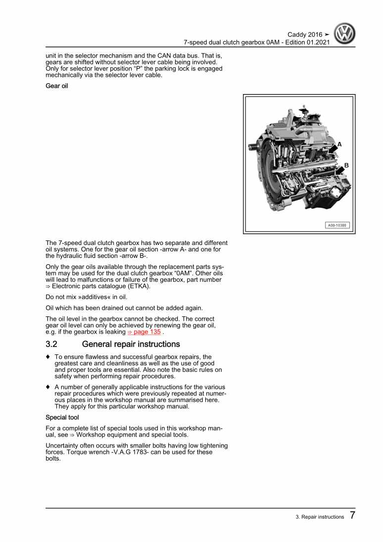
Beispielseite für Reparaturanleitung 7-speed dual clutch gearbox 0AM

Für Caddy (2016)

13,63 € Details

Wheels and Tyres Guide

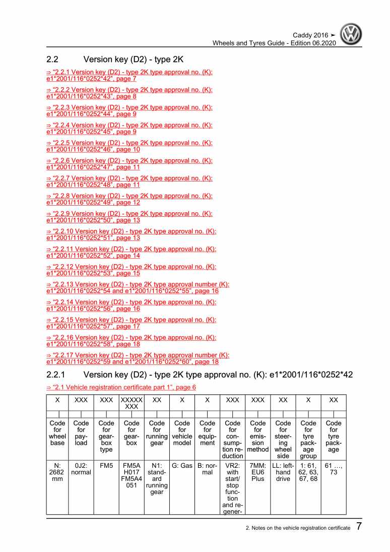
Beispielseite für Reparaturanleitung Wheels and Tyres Guide

Für Caddy (2016)

16,48 € Details

-Fitting locations: special vehicles

Beispielseite für Reparaturanleitung -Fitting locations: special vehicles

Für Caddy (2016)

4,58 € Details

Fuel supply system - natural gas engines

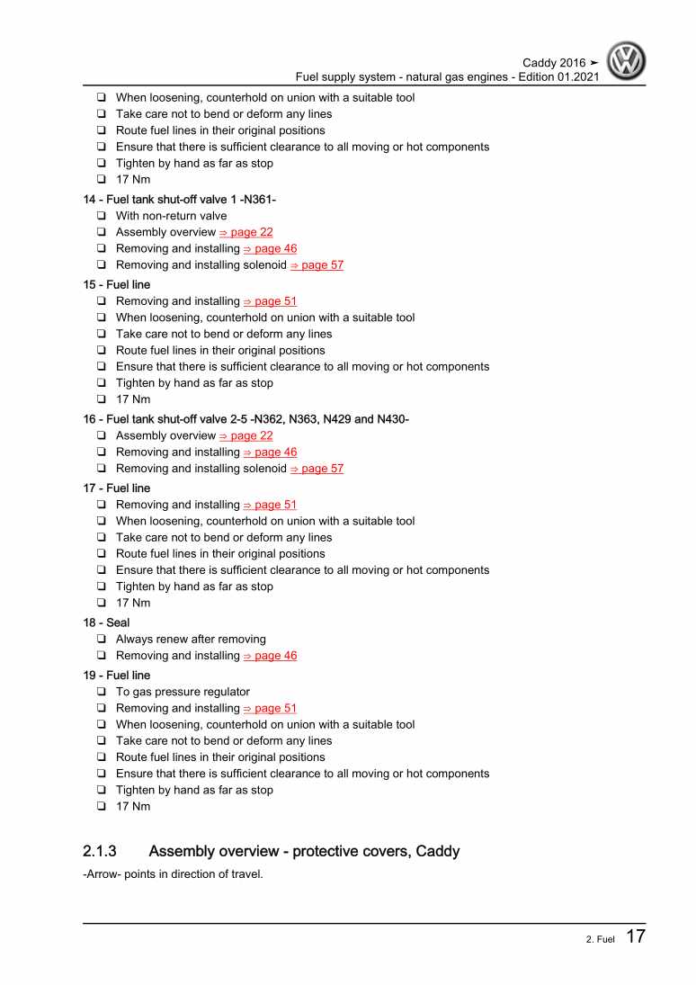
Beispielseite für Reparaturanleitung Fuel supply system - natural gas engines

Für Caddy (2016)

11,46 € Details

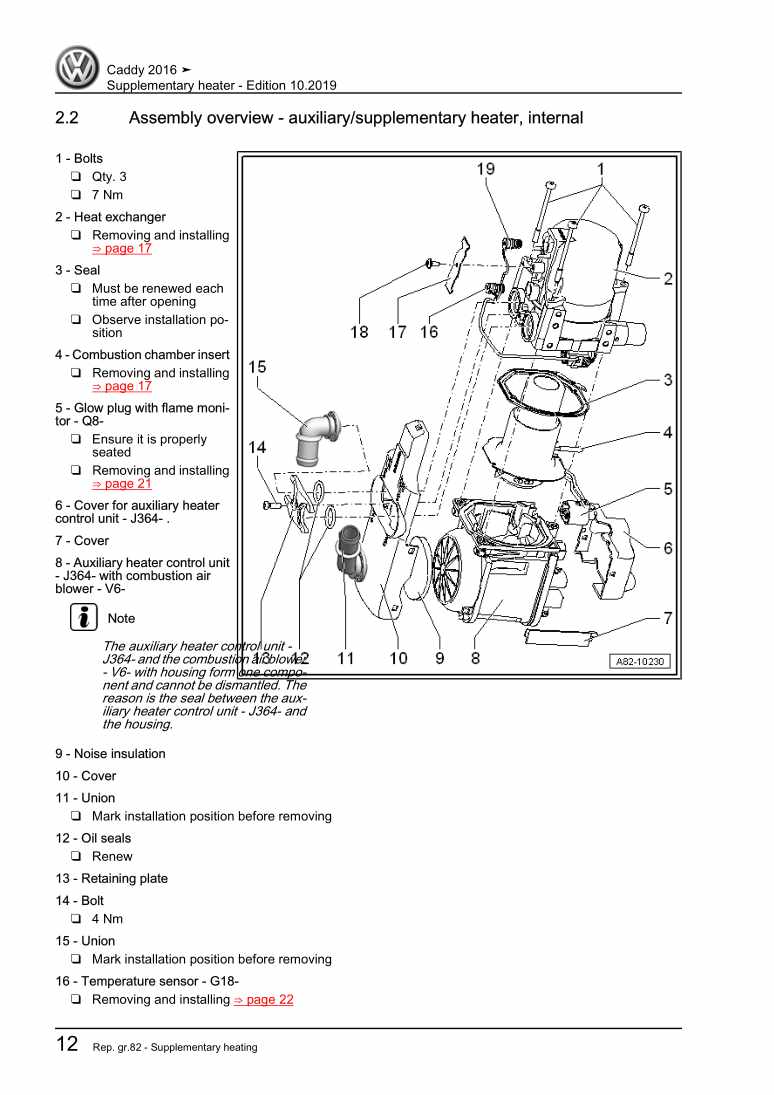
Supplementary heater

Beispielseite für Reparaturanleitung Supplementary heater

Für Caddy (2016)

6,12 € Details

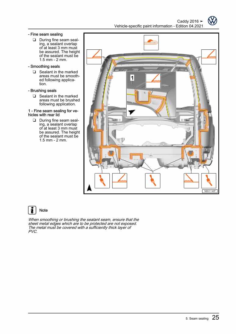
Vehicle-specific paint information

Beispielseite für Reparaturanleitung Vehicle-specific paint information

Für Caddy (2016)

5,41 € Details

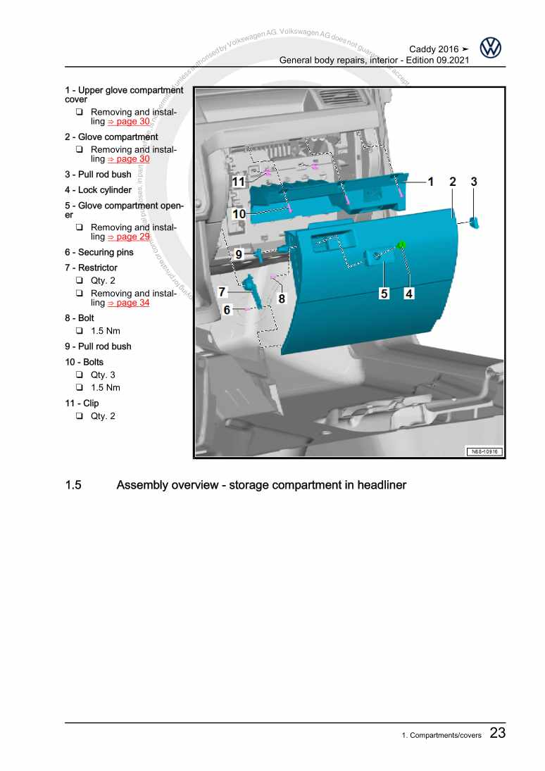
General body repairs, interior

Beispielseite für Reparaturanleitung General body repairs, interior

Für Caddy (2016)

30,13 € Details

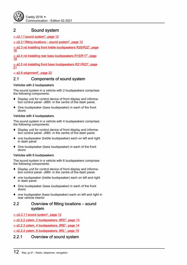
Communication

Beispielseite für Reparaturanleitung Communication

Für Caddy (2016)

9,91 € Details

3-cylinder direct-injection engine (1.0 l engine, 4V, EA 211)

Beispielseite für Reparaturanleitung 3-cylinder direct-injection engine (1.0 l engine, 4V, EA 211)

Für Caddy (2016)

25,05 € Details

Unsere Best Seller

Schon gewusst? Wir bieten auch originale Autoteile an.

Autoteil 4G0919268H Aufnahme

4G0919268H

Aufnahme

21,35 €

Details
Autoteil 5Q0713128A Schalter

5Q0713128A

Schalter

46,12 €

Details
Autoteil 7H7067081 Gasdrfeder

7H7067081

Gasdrfeder

35,85 €

Details
Autoteil 8S0827990 Adapter

8S0827990

Adapter

67,54 €

Details
Autoteil 1S0823363F Stuetze

1S0823363F

Stuetze

19,43 €

Details

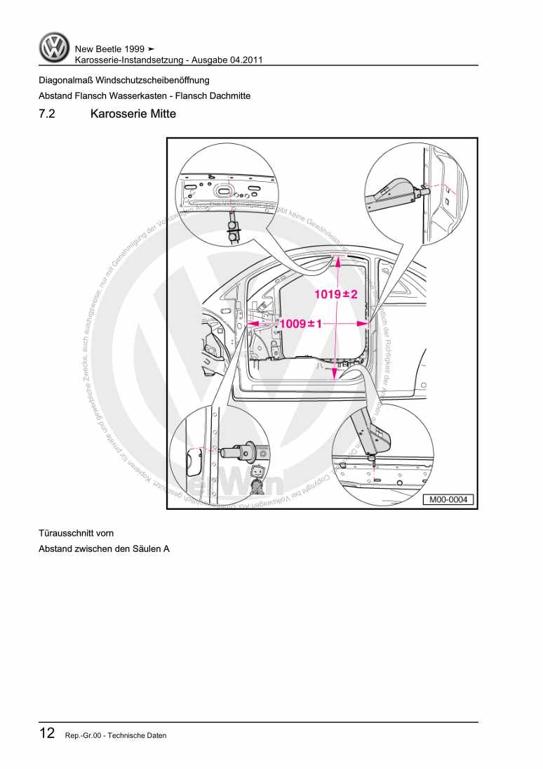
Karosserie-Instandsetzung

Beispielseite für Reparaturanleitung Karosserie-Instandsetzung

Für New Beetle / New Beetle (USA) (1998 - 2007) / New Beetle (Europe) (1999 - 2002)

10,12 € Details

Nr. 528: Der Erdgasantrieb im Golf/Golf Variant TGI BlueMotion

Beispielseite für Reparaturanleitung Nr. 528: Der Erdgasantrieb im Golf/Golf Variant TGI BlueMotion

5,26 € Details

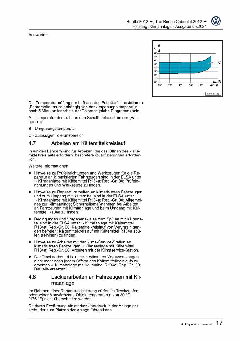
Heizung, Klimaanlage

Beispielseite für Reparaturanleitung Heizung, Klimaanlage

Für Beetle (NBL) Limousine (2012) / Beetle (NBC) Cabrio (2012)

15,89 € Details

image/svg+xml Über Clonck

Originale Reparaturanleitungen und Ersatzteile

Unsere Reparaturanleitungen sind Originale, kommen direkt von Volkswagen und erfüllen die höchsten Qualitätsstandards.

In unserem Originalteile-Shop verkaufen wir hochwertige Originalersatzteile der Fahrzeughersteller. Mithilfe der Suche gibst du die gewünschte Teilenummer (OE-Nummer) ein und bestellst schnell und einfach das benötigte Ersatzteil.

Höchste Qualitätsstandards

Bei Clonck wollen wir Autoschrauber und Kfz-Profis glücklich machen. Aus diesem Grund findest du bei Clonck ausschließlich professionelle und hochwertige Reparaturanleitungen, mit deren Hilfe du dein Fahrzeug fachgerecht reparieren kannst.

Unsere Partner

Autohaus Schmidt GmbH
Automag GmbH Filiale Laim
KFZ-VERLAG GmbH
Zimpel und Franke GmbH

Clonck: Der Autoreparatur-Shop - gibt's auch als App!

Clonck App Logo Play Store

Clonck: Passende Autoteile für deine Autoreparatur

4,5 90

Mit Clonck bestellst du die richtigen Originalersatzteile im Handumdrehen.

  • Fahrzeugmodell hinzufügen
  • Baugruppe auswählen
  • Fahrzeug-Identifizierungsnummer (FIN) eingeben
  • Über 5.000 originale Reparaturanleitungen einsehen
Jetzt App starten
Clonck App Preview Auto Mobiltelefon Autoteile