Technical data
11 Safety information
11.1 Safety precautions when working on the cooling system
11.2 Safety measures when working on fuel supply
21.4 Safety precautions when working on injection system
32 Identification
42.1 Engine number/engine data
43 General information
53.1 General notes on injection
53.2 General notes on the lubrication system
53.3 General notes on fuel system
64 Repair instructions
84.1 Rules for cleanliness when working on fuel supply system
84.2 Rules for cleanliness when working on injection system
84.3 Rules for cleanliness when working on turbocharger
94.4 Foreign objects in engine
9Removing and installing engine
101 Removing and installing engine
101.1 Removing engine
101.2 Separating engine from gearbox
221.3 Separating engine from dual clutch gearbox
231.4 Securing engine on engine and gearbox support
251.5 Installing engine
262 Assembly mountings
322.1 Assembly overview - assembly mountings
322.2 Removing and installing engine mounting
352.3 Removing and installing engine bracket
372.4 Supporting engine in installation position
402.5 Adjusting assembly mountings
433 Engine cover panel
473.1 Removing and installing engine cover
47Crankshaft group
481 Cylinder block (pulley end)
481.1 Assembly overview - cylinder block
481.2 Assembly overview - sealing flange, belt pulley end
501.3 Assembly overview - poly V-belt drive without air conditioner compressor
511.4 Assembly overview - poly V-belt drive with air conditioning compressor
521.5 Assembly overview - ancillary bracket
531.6 Removing and installing sealing flange on pulley end
531.7 Renewing crankshaft oil seal - belt pulley end
561.8 Removing and installing bracket for ancillaries
581.9 Removing and installing poly V-belt without air conditioner compressor
611.10 Removing and installing poly V-belt with air conditioner compressor
611.11 Removing and installing tensioner for poly V-belt
631.12 Removing and installing vibration damper
642 Cylinder block, gearbox end
662.1 Assembly overview - flywheel
662.2 Removing and installing flywheel
672.3 Removing and installing sealing flange on gearbox side
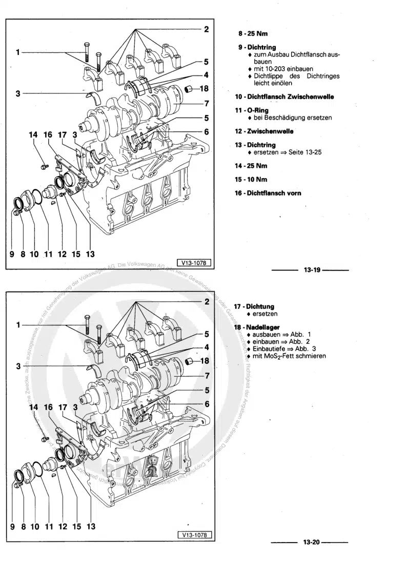
683 Crankshaft
763.1 Assembly overview - crankshaft
763.2 Crankshaft dimensions
773.3 Renewing needle bearing in crankshaft
774 Pistons and conrods
794.1 Assembly overview - pistons and conrods
794.2 Checking pistons and cylinder bores
814.3 Piston and cylinder dimensions
824.4 Separating new conrod
824.5 Measuring piston projection at TDC
834.6 Checking radial clearance of conrods
844.7 Removing and installing oil spray jets
85Cylinder head, valve gear
871 Cylinder head
871.1 Assembly overview - cylinder head
871.2 Assembly overview - cylinder head cover
891.3 Removing and installing cylinder head
911.4 Removing and installing cylinder head cover
1061.5 Removing and installing injector seals
1111.6 Removing and installing vacuum pump
1141.7 Checking compression
1152 Fully enclosing toothed belt guard
1172.1 Assembly overview - fully enclosing toothed belt guard
1172.2 Removing and installing upper toothed belt guard (fully enclosing)
1182.3 Removing and installing lower toothed belt guard (fully enclosed)
1192.4 Removing and installing rear toothed belt guard (fully enclosing)
1203 Toothed belt drive
1253.1 Assembly overview - toothed belt drive
1253.2 Removing and installing toothed belt
1274 Valve gear
1414.1 Assembly overview - valve gear
1414.2 Removing and installing camshafts
1444.3 Measuring axial play of camshaft
1514.4 Measuring radial play of camshaft
1524.5 Removing and installing camshaft oil seal
1524.6 Checking hydraulic compensation elements
1554.7 Removing and installing valve stem seals
1554.8 Removing and installing valve stem seals with cylinder head removed
1595 Inlet and exhaust valves
1635.1 Reworking valve seats
1635.2 Checking valve guides
1635.3 Checking valves
1645.4 Valve dimensions
164Lubrication
1651 Sump, oil pump
1651.1 Assembly overview - sump/oil pump
1651.2 Removing and installing sump
1671.3 Removing and installing oil pump
1711.4 Engine oil:
1731.5 Removing and installing oil level and oil temperature sender G266
1731.6 Measuring oil consumption
1742 Engine oil cooler
1752.1 Removing and installing engine oil cooler
1753 Oil filter, oil pressure switch
1793.1 Assembly overview - oil filter housing with engine oil cooler
1793.2 Removing and installing oil filter housing
1803.3 Removing and installing oil pressure switch F1
1833.4 Checking oil pressure switch
1853.5 Checking oil pressure
1864 Oil circuit
1884.1 Assembly overview - oil circuit
1884.2 Removing and installing oil supply line
189Cooling
1931 Cooling system/coolant
1931.1 Connection diagram - coolant hoses
1931.2 Draining and adding coolant
1941.3 Checking cooling system for leaks
2021.4 Checking engine oil cooler for leaks
2042 Coolant pump, regulation of cooling system
2062.1 Assembly overview - coolant pump, thermostat
2062.2 Assembly overview - coolant pump and thermostat, from week 22/2011
2072.3 Removing and installing coolant pump
2072.4 Removing and installing 4/2-way valve with thermostat
2082.5 Removing and installing coolant temperature sender G62
2142.6 Removing and installing radiator outlet coolant temperature sender G83
2152.7 Removing and installing coolant circulation pump 2 V178
2163 Radiator, radiator fan
2193.1 Assembly overview - radiator/radiator fan
2193.3 Removing and installing radiator
2214 Coolant pipes
2244.1 Assembly overview - coolant pipes
2244.2 Removing and installing lower coolant pipe
2254.3 Removing and installing upper coolant pipe
2294.4 Removing and installing left coolant pipe
2304.5 Removing and installing right coolant pipe
232Turbocharging/supercharging
2351 Turbocharger
2351.1 Assembly overview - turbocharger
2351.2 Removing and installing turbocharger
2391.3 Removing and installing charge pressure control solenoid valve N75
2442 Charge air system
2472.1 Assembly overview - charge air system
2472.2 Assembly overview - charge-air hose connections
2482.3 Removing and installing charge air cooler
2492.4 Removing and installing charge air pipe
2512.5 Removing and installing charge air pressure sender G31 / intake air temperature sender G42
2522.6 Checking charge air system for leaks
252Mixture preparation - injection
2561 Injection system
2561.1 Schematic overview - fuel system
2561.2 Overview of fitting locations - injection system
2581.3 Assembly overview - fuel system
2671.4 Checking fuel system for leaks
2701.5 Filling/bleeding fuel system
2702 Vacuum system
2722.1 Connection diagram - vacuum system
2722.2 Checking vacuum system
2733 Injectors/high-pressure accumulator (rail)
2813.1 Overview - fuel return lines
2813.2 Assembly overview - injectors
2823.3 Removing and installing high-pressure lines
2823.4 Removing and installing fuel rail
2883.5 Removing and installing injectors
2923.6 Adapting correction values for injectors
2973.7 Replacing O-ring of fuel return lines
2983.8 Check pressure retention valve in fuel return line
2983.9 Checking return flow rate of injectors at starter speed
3003.10 Testing injectors
3014 High-pressure pump
3034.1 Assembly overview - high-pressure pump
3034.2 Removing and installing high-pressure pump
3044.3 Pressure testing high-pressure pump
3084.4 Checking high-pressure pump
3105 Intake manifold
3135.1 Assembly overview - intake manifold
3135.2 Removing and installing intake manifold
3145.3 Removing and installing throttle valve module GX3
3186 Air filter
3206.1 Assembly overview - air filter housing
3206.2 Removing and installing air filter housing
3217 Lambda probe
3237.1 Removing and installing Lambda probe G39
3238 Senders and sensors
3258.1 Removing and installing air mass meter G70
3258.2 Removing and installing pressure differential sender G505
3268.3 Removing and installing fuel pressure regulating valve N276
3268.4 Checking fuel pressure regulating valve N276
3298.5 Removing and installing fuel pressure sender G247
3318.6 Checking fuel pressure sender G 247
3348.7 Checking fuel metering valve N 290
3359 Engine control unit
3369.1 Removing and installing engine control unit J623
3369.2 Removing and installing anti-theft engine control unit J623
337Exhaust system
3401 Exhaust pipes and silencers
3401.1 Assembly overview - silencers
3401.2 Separating exhaust pipes from silencers
3411.3 Aligning exhaust system free of stress
3421.4 Installation position of clamp
3432 Emission control
3442.1 Assembly overview - catalytic converter
3442.2 Assembly overview - particulate filter
3462.3 Removing and installing particulate filter
3473 Exhaust gas temperature regulation
3523.1 Assembly overview - exhaust gas temperature regulation
3523.2 Removing and installing exhaust gas temperature sender 1 G235
3533.3 Removing and installing exhaust gas temperature sender 3 G495
3543.4 Removing and installing exhaust gas temperature sender 4 G648
3564 Exhaust gas recirculation
3594.1 Assembly overview - exhaust gas recirculation
3594.2 Checking changeover for exhaust gas recirculation cooler
3604.3 Removing and installing exhaust gas recirculation cooler
3614.4 Checking exhaust gas recirculation cooler for leaks
3634.5 Cleaning exhaust gas recirculation system
364Glow plug system
3711 Glow plug system
3711.1 Removing and installing glow plug
3711.2 Checking glow plugs
3731.3 Removing and installing automatic glow period control unit J179
3731.4 Removing and installing engine speed sender G28
3741.5 Removing and installing Hall sender G40
375