Technical data
11 \--- Change history ---
12 Safety instructions
22.1 Safety measures regarding work on the fuel supply
22.2 Safety measures in test drives using testing and measurement devices
32.3 Safety measures when working on the ignition system
42.4 Safety measures when working on the exhaust system
42.5 Safety measures when working on the cooling system
43 Identification
63.1 Engine number/engine characteristics
64 Repair instructions
84.1 Cleanliness rules
84.2 General instructions
84.3 General repair instructions
94.4 Foreign bodies on the engine
94.5 Contact corrosion
94.6 Connection installation and fastening
104.7 Radiator and capacitor installation
104.8 Check the vacuum system
10Removing and installing engine
111 Engine - remove and install
111.1 Engine - removal
111.2 Engine - separate gearbox
231.3 Engine - secure to engine and gearbox support
251.4 Engine - installation
281.5 Engine - remove and install, summarized instructions
312 Power-drive unit supports
342.1 Power unit brackets - assembly overview
342.2 Power unit bracket (engine side) - remove and install
372.3 Drive-train mounting (gearbox side) - remove and install
382.4 Pendulum support (torque limiter) - remove and install
402.5 Support the engine in assembly position
422.6 Drive train mountings - adjust
472.7 Drive train mounting adjustment - check
49Crankshaft group
511 Cylinder block (pulley side)
511.1 Poly-V belt mechanism - assembly overview
511.2 Poly-V belt - remove and install
531.3 Poly-V belt tensioner - remove and install
551.4 Crankshaft pulley (vibration damper) - remove and install
551.5 Engine console - remove and install
591.6 Crankshaft seal (pulley side) - replace
642 Cylinder block (gearbox side)
672.1 Cylinder block (gearbox side) - assembly overview
672.2 Flywheel - remove and install
692.3 Crankshaft flange (flywheel side) - replace
713 Crankshaft
843.1 Crankshaft - dimensions
844 Pistons and conrods - remove and install
854.1 Pistons and conrods - assembly overview
854.2 Pistons - remove and install
884.3 Pistons, rings, and cylinders - check
894.4 Conrod and cap (new part) - separate
924.5 Conrod radial clearance - check
924.6 Oil spray jet and valve - remove and install
93Cylinder head, valve gear
951 Engine cylinder head
951.1 Engine cylinder head - assembly overview
951.2 Cylinder head cover with exhaust and inlet camshafts - assembly overview
971.3 Cylinder head - remove and install
991.4 Cylinder head - remove and install, summarized instructions
1051.5 Cylinder head cover with exhaust and inlet camshafts - remove and install
1071.6 Cylinder compression - check
1132 Toothed belt drive
1162.1 Console, upper and lower cover of the toothed belt - assembly overview
1162.2 Toothed belt - assembly overview
1162.3 Toothed belt - remove and install
1182.4 Valve timing - check
1222.5 Camshaft toothed belt - remove
1283 Camshaft mechanism
1433.1 Camshaft mechanism - assembly overview
1433.2 Crankshaft - check axial clearance
1453.3 Camshaft gasket (pulley side) - replace
1463.4 Intake and exhaust valve camshaft regulator/gear - remove and install
1543.5 Camshaft adjustment valve 1 N205 - remove and install
1643.6 Valve stem sealant - replace
1654 Inlet and exhaust valves
1784.1 Valve guides - check
1784.2 Valves - check
1794.3 Valve dimensions
179Lubrication
1801 Crankcase/oil pump
1801.1 Crankcase/oil pump - assembly overview
1801.2 Lower sump - remove and install
1851.3 Upper crankcase - remove and install
1871.4 Oil pump - remove and install
1911.5 Engine oil
1932 Engine crankcase ventilation
1952.1 Engine crankcase ventilation - assembly overview
1952.2 Crankcase ventilation device - remove and install
1963 Oil filter/Oil pressure switch F378
2003.1 Oil filter/Oil pressure switch F378 – assembly overview
2003.2 Oil filter - remove and install
2003.3 Oil pressure switch F378 – remove and install
2013.4 Oil pressure and Oil pressure switch F378 – check
203Cooling
2061 Cooling system/coolant
2061.1 Hose connection diagram for cooling system
2061.2 Cooling system - check air-tightness
2071.3 Coolant tank flap - check safety valve
2101.4 Cooling system - drainage and replenishment
2112 Water pump/coolant adjustment
2202.1 Water pump/thermostatic valves - assembly overview
2202.2 Air intake cooling pump V188 - assembly overview
2232.3 Coolant temperature sensor - assembly overview
2242.4 Air intake cooling pump V188 - remove and install
2252.5 Water pump - remove and install
2272.6 Thermostats - remove and install
2322.7 Water pump toothed belt - remove and install
2382.8 Water pump sprocket - remove and install
2412.9 Coolant temperature sensor G62 - remove and install
2422.10 Coolant temperature sensor on the radiator outlet G83 - remove and install
2443 Cooling system pipes
2463.1 Coolant system line - assembly overview
2463.2 Cooling system line - remove and install
2464 Radiator/Radiator fan
2494.1 Radiator - assembly overview
2494.2 Fan cowl and radiator fan - assembly overview
2514.3 Radiator - remove and install
2524.4 Fan housing - remove and install
2544.5 Radiator fan V7 - remove and install
2554.6 Charge air cooling system radiator - remove and install
256Fuel supply system
2601 Fuel tank
2601.1 Fuel tank - assembly overview
2601.2 Fuel tank - remove and install
2621.3 Fuel tank - drain
2692 Fuel supply unit/Fuel level sensor
2802.1 Fuel pump (pre-supply pump) G6/Fuel gauge sensor G - assembly overview
2802.2 Fuel pump (pre-supply pump) G6/Fuel gauge sensor G - remove and install
2822.3 Fuel gauge sensor G - remove and install
2872.4 Installation opening cover - remove and install
2883 Plug-in connectors
2903.1 Plug-in connectors - disconnect
2904 Fuel filter
2964.1 Fuel filter - remove and install
2965 Activated charcoal system
2985.1 Activated charcoal filter system - assembly overview
2985.2 Activated charcoal filter - remove and install
3005.3 Fuel tank ventilation - check
3016 Accelerator activation
3086.1 Accelerator pedal module - assembly overview
3086.2 Accelerator pedal module GX2 - remove and install
3087 Fuel system pressurisation pump G6
3107.1 Fuel system pressurisation pump G6 - check
3107.2 Fuel pump control unit J538 - remove and install
3308 Fuel lines
3328.1 Fuel lines - remove and install
332Turbocharging/supercharging
3371 Exhaust gas turbocharger
3371.1 Exhaust gas turbocharger - Assembly overview
3371.2 Exhaust gas turbocharger - remove and install
3411.3 Exhaust gas turbocharger - remove and install, summarized instructions
3461.4 Load pressure control V465 - remove and install
3471.5 Turbocharger nozzle - remove and install
3482 Supercharging air system
3522.1 Supercharging air system - Assembly overview
3522.2 Air duct - remove and install
3552.3 Supercharging air intercooler - remove and install
3562.4 Load pressure sensor GX26 - remove and install
3572.5 Charge air system - check air-tightness
358Mixture preparation - injection
3611 Injection system
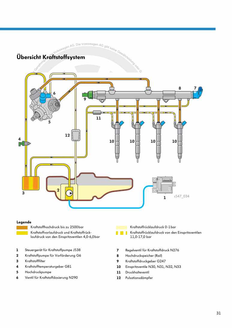
3611.1 Injection system - assembly overview
3611.2 Fuel system - relieve pressure
3672 Air cleaner
3692.1 Air filter - assembly overview
3692.2 Air filter - remove and install
3713 Intake manifold
3743.1 Intake manifold - assembly overview
3743.2 Intake manifold - remove and install
3763.3 Throttle butterfly valve control unit GX3 - remove and install
3803.4 Throttle valve control unit GX3 - clean
3814 Injection valves
3834.1 Fuel rail with injection valves - assembly overview
3834.2 Fuel distributor - removal and installation
3854.3 Injection valves - remove and install
3864.4 Injectors - remove and install, summarized instructions
3934.5 Injection valves - clean
3955 Transmitters and sensors
3975.1 Intake manifold sensor GX9 - remove and install
3975.2 Fuel pressure sensor G247 - remove and install
3985.3 Fuel pressure sensor G247 - check
3996 High pressure pump
4036.1 High pressure pump - assembly overview
4036.2 High pressure pump - remove and install
4056.3 High pressure line - remove and install
4077 Lambda probe
4107.1 Lambda probe - assembly overview
4108 Engine control unit J623
4148.1 Engine control unit J623 - remove and install
414Exhaust system
4161 Silencer/exhaust pipes
4161.1 Silencer - assembly overview
4161.2 Silencer/exhaust pipes - detach
4171.3 Centre silencer with rear silencer - remove and install
4191.4 Centre silencer - remove and install
4231.5 Rear silencer - remove and install
4251.6 Exhaust system - tension free alignment
4261.7 Exhaust system - check tightness
4261.8 Pipe clamp installation position
4272 Exhaust system
4282.1 Emission control - assembly overview
4282.2 Catalytic converter - remove and install
431Ignition system
4351 Ignition system
4351.1 Ignition system - assembly overview
4351.2 Ignition coils with final power stage - assembly overview
4371.3 Spark plugs Q - technical data
4381.4 Ignition coil with final power stage - remove and install
4381.5 Knock sensor 1 G61 - remove and install
4411.6 Hall Sensor G40 - remove and install
4431.7 Engine speed sensor G28 - remove and install
443
