DER AUTOREPARATUR-SHOP
0
Home » Anleitungen » 4-Cyl. injection engine (1.6 l)
  • Beispielseite für Reparaturanleitung 4-Cyl. injection engine (1.6 l)
  • Beispielseite für Reparaturanleitung 2 4-Cyl. injection engine (1.6 l)
  • Beispielseite für Reparaturanleitung 3 4-Cyl. injection engine (1.6 l)
  • Beispielseite für Reparaturanleitung 4-Cyl. injection engine (1.6 l)
  • Beispielseite für Reparaturanleitung 2 4-Cyl. injection engine (1.6 l)
  • Beispielseite für Reparaturanleitung 3 4-Cyl. injection engine (1.6 l)

4-Cyl. injection engine (1.6 l)

Für GOL BR / Voyage BR / Saveiro Cab. Dupla [BR] / Saveiro Cab. Sim. / Saveiro Cab. Est. / Voyage [BR] / Gol [BR]

Original VW-Reparaturanleitung


18,51 €inkl. 7% MwSt.

Sofort als Download verfügbar

Sprache: English

Digitale PDF Version

6.963 KB

226 Seiten

Detaillierte technische Daten

Sofort lesbar

Diese Reparaturanleitung umfasst: Engine - remove and install, Power-drive unit supports, Cylinder block (pulley side), Crankshaft, Toothed belt drive, Lubrication system components, Oil filter / Oil pressure switch F1, Radiator / Radiator fan, Fuel supply unit / fuel level sensor, Engine power electronic adjustment (electronic accelerator), Injection valves, Air cleaner, Intake manifold und READINESS code. Mehr anzeigen
Sichere Zahlung per PayPal, Kreditkarte, Lastschrift, Sofort-Überweisung oder Giropay
PayPal Logo SEPA Lastschrift Logo Giropay Logo Sofort Überweisung Logo

Reparaturanleitung 4-Cyl. injection engine pdf Download mit dem Inhalt:

Kapitelübersicht

  • Technical data
    1
  • 1 \--- Change history ---
    1
  • 2 Safety instructions
    2
  • 2.1 Safety measures regarding work on the fuel supply
    2
  • 2.2 Safety measures for working on the injection and ignition system
    2
  • 3 Repair instructions
    4
  • 3.1 Cleanliness rules
    4
  • 4 Technical Data
    5
  • 4.1 Engine number
    5
  • 4.2 Engine characteristics
    5
  • Removing and installing engine
    7
  • 1 Engine - remove and install
    7
  • 1.1 Engine - removal
    7
  • 1.2 Engine - fasten to assembly stand
    17
  • 1.3 Engine - installation
    18
  • 2 Power-drive unit supports
    21
  • 2.1 Power unit brackets - assembly overview
    21
  • 2.2 Drive train mountings - alignment
    23
  • Crankshaft group
    26
  • 1 Cylinder block (pulley side)
    26
  • 1.1 Poly-V belt drive (elastic) - assembly overview
    27
  • 1.2 Cylinder block (pulley side) - assembly overview
    29
  • 1.3 Seal lid - replace
    31
  • 1.4 Poly-V belt (elastic) - remove and install
    31
  • 1.5 Crankshaft pulley - removal and installation
    36
  • 1.6 Crankshaft seal (pulley side) - replace
    36
  • 2 Cylinder block, gearbox side
    40
  • 2.1 Crankshaft and flywheel flanges - assembly overview
    40
  • 2.2 Flywheel - remove and install
    42
  • 2.3 Crankshaft flange (flywheel side) with Engine speed sensor G28 rotor - replace
    43
  • 3 Crankshaft
    55
  • 3.1 Crankshaft - assembly overview
    55
  • 3.2 Identifying engine bearing shells
    56
  • 3.3 Colour codes
    58
  • 3.4 Crankshaft - dimensions
    58
  • 4 Pistons and conrods
    59
  • 4.1 Pistons and conrods - assembly overview
    59
  • 4.2 Pistons, rings, and cylinders - check
    61
  • 4.3 Piston and cylinder - dimensions
    64
  • Cylinder head, valve gear
    65
  • 1 Engine cylinder head
    65
  • 1.1 Engine cylinder head - assembly overview
    65
  • 1.2 Cylinder head - remove and install
    68
  • 1.3 Compression - check
    73
  • 2 Toothed belt drive
    76
  • 2.1 Toothed belt semi-automatic tensioning pulley - check
    76
  • 2.2 Toothed belt - remove and install, adjust
    77
  • 3 Camshaft
    84
  • 3.1 Camshaft - assembly overview
    84
  • 3.2 Camshaft - check axial clearance
    87
  • 3.3 Camshaft seal - replace
    89
  • 3.4 Camshaft and cylinder head cover - remove and install
    94
  • 3.5 Valve stem sealant - replace
    99
  • 4 Inlet and exhaust valves
    102
  • 4.1 Valve seat - trim
    102
  • 4.2 Valve guides - check
    104
  • Lubrication
    106
  • 1 Lubrication system components
    106
  • 1.1 Lubricating system components - assembly overview
    106
  • 1.2 Engine oil
    109
  • 1.3 Crankcase - remove and install
    110
  • 1.4 Oil pump - remove and install
    113
  • 2 Oil filter / Oil pressure switch F1
    118
  • 2.1 Oil pressure switch F1 - remove and install
    118
  • 2.2 Oil pressure and Oil pressure switch F1 - check
    118
  • 2.3 Oil filter - replace
    120
  • Cooling
    123
  • 1 Cooling system components
    123
  • 1.1 Hose connection diagram for cooling system
    123
  • 1.2 Cooling system - drainage and replenishment
    124
  • 1.3 Cooling system - check air-tightness
    133
  • 1.4 Coolant tank flap - check safety valve
    135
  • 2 Water pump / coolant adjustment
    137
  • 2.1 Water pump - assembly overview
    137
  • 2.2 Thermostat valve - assembly overview
    138
  • 2.3 Water pump - remove and install
    140
  • 3 Radiator / Radiator fan
    143
  • 3.1 Radiator / Radiator fan - assembly overview
    143
  • 3.2 Radiator - remove and install
    145
  • 3.3 Cowling with Radiator fan V7 - remove and install
    146
  • 3.4 Radiator fan V7 - remove and install
    147
  • Fuel supply system
    148
  • 1 Fuel supply system components
    148
  • 1.1 Fuel tank components with accessories and fuel filter - assembly overview
    148
  • 1.2 Cold start system components - remove and install
    154
  • 1.3 Fuel tank - remove and install
    155
  • 1.4 Fuel reservoir (EU5) - remove and install
    157
  • 2 Fuel supply unit / fuel level sensor
    161
  • 2.1 Fuel pump (pre-supply pump) G6 - remove and install
    161
  • 2.2 Fuel gauge sensor G - remove and install
    164
  • 3 Activated charcoal filter system
    165
  • 3.1 Operation
    165
  • 3.2 Activated charcoal filter system - assembly overview
    165
  • 3.3 Magnetic valve 1 for activated charcoal filter N80 - remove and install
    166
  • 3.4 Fuel tank ventilation - check
    167
  • 4 Engine power electronic adjustment (electronic accelerator)
    169
  • 4.1 Engine power electronic adjustment (electronic accelerator) - assembly overview
    169
  • 4.2 Electronic accelerator system operation
    169
  • 5 Fuel pump (pre-supply pump) G6
    171
  • 5.1 Voltage supply of the Fuel pump (pre-supply pump) G6 - check
    173
  • 5.2 Fuel supply system output - check
    175
  • 5.3 Current consumption - check
    180
  • 5.4 Fuel pump (pre-supply pump) G6 retention valve - check
    180
  • Mixture preparation - injection
    182
  • 1 Injection system
    182
  • 1.1 General instructions regarding the injection system
    182
  • 1.2 Injection system - assembly overview
    182
  • 1.3 Injection components - assembly overview
    184
  • 1.4 Technical Data
    187
  • 2 Injection valves
    188
  • 2.1 Fuel rail with injectors - assembly overview
    188
  • 2.2 Injection valves - check
    188
  • 2.3 Injection valves - clean
    193
  • 3 Air cleaner
    195
  • 3.1 Air filter - assembly overview
    195
  • 3.2 Air filter - remove and install
    196
  • 4 Intake manifold
    198
  • 4.1 Intake manifold - assembly overview
    198
  • 4.2 Throttle valve control unit J338 - clean
    199
  • 5 Component checks
    201
  • 5.1 Supply system pressure, fuel pressure gauge and residual pressure - check
    201
  • 6 READINESS code
    207
  • 6.1 Creating and Interpreting the READINESS code
    207
  • 7 Engine control unit J623
    208
  • 7.1 Engine control unit J623 - remove and install
    208
  • 7.2 Adjust components
    209
  • 7.3 Check the event memory in the Engine control unit J623 and delete it
    210
  • Exhaust system
    212
  • 1 Rear muffler
    212
  • 1.1 Rear muffler - assembly overview
    212
  • 1.2 Silencer/exhaust pipes - detach
    212
  • 1.3 Exhaust system - tension free alignment
    213
  • 1.4 Pipe clamp installation position
    214
  • Glow plug system
    218
  • 1 Ignition system
    218
  • 1.1 General instructions regarding the ignition system
    218
  • 1.2 Ignition system - assembly overview
    218
  • 1.3 Spark plugs Q - test data
    220
Hersteller­bezeichnung 4-Cyl. injection engine (1.6 l)
Hersteller Volkswagen
Passend für GOL BR (2017) / Voyage BR (2017) / Saveiro Cab. Dupla [BR] (2017 >) / Saveiro Cab. Sim. (2017 >) / Saveiro Cab. Est. (2017 >) / Voyage [BR] (2019 >) / Gol [BR] (2019 >)
Passende Autotypen 5U5, 5UD, 5UF, 5UE, 5UG, 5U7
Motor­kennbuchstaben CFZA
Kategorie Reparaturanleitung

Im Moment sind noch keine Bewertungen für dieses Produkt vorhanden.

Ähnliche Reparaturanleitungen

General body repairs, interior
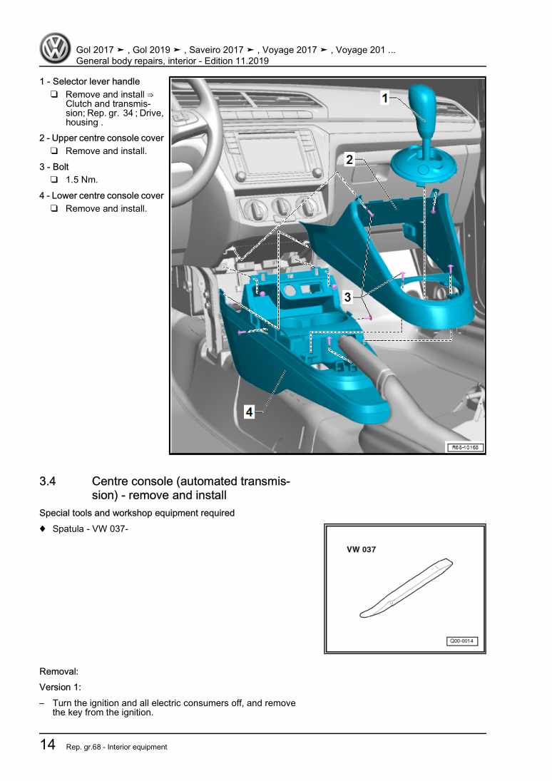
Beispielseite für Reparaturanleitung General body repairs, interior

Für GOL BR (2017) / Voyage BR (2017) / Saveiro Cab. Dupla [BR] (2017 >) / Saveiro Cab. Sim. (2017 >) / Saveiro Cab. Est. (2017 >) / Voyage [BR] (2019 >) / Gol [BR] (2019 >)

23,77 € Details

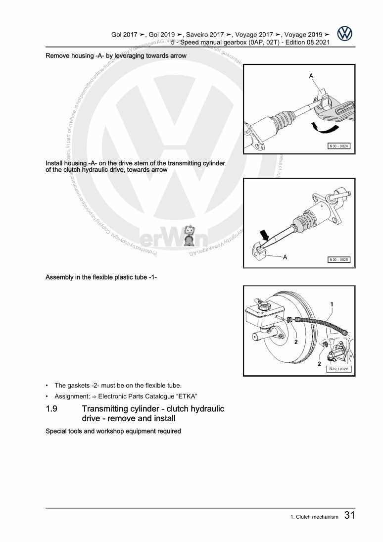
5 - Speed manual gearbox (0AP, 02T)

Beispielseite für Reparaturanleitung 5 - Speed manual gearbox (0AP, 02T)

Für GOL BR (2017) / Voyage BR (2017) / Saveiro Cab. Dupla [BR] (2017 >) / Saveiro Cab. Sim. (2017 >) / Saveiro Cab. Est. (2017 >) / Voyage [BR] (2019 >) / Gol [BR] (2019 >)

16,40 € Details

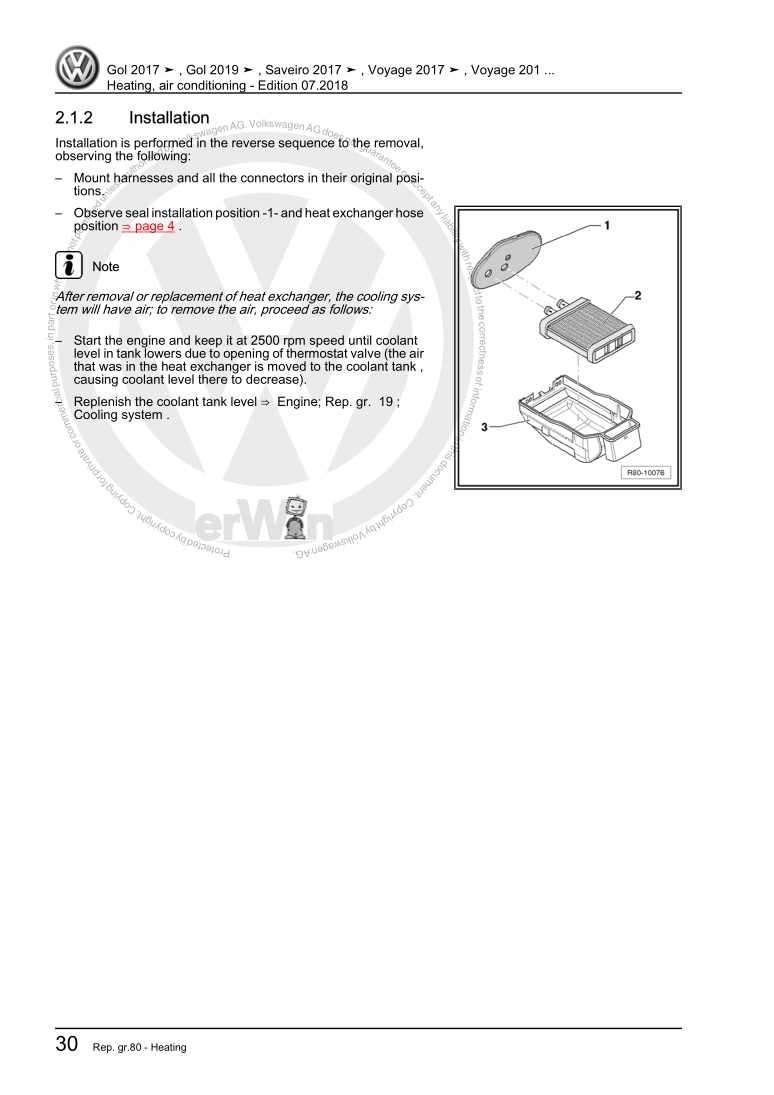
Heating, air conditioning

Beispielseite für Reparaturanleitung Heating, air conditioning

Für GOL BR (2017) / Voyage BR (2017) / Saveiro Cab. Dupla [BR] (2017 >) / Saveiro Cab. Sim. (2017 >) / Saveiro Cab. Est. (2017 >) / Voyage [BR] (2019 >) / Gol [BR] (2019 >)

12,18 € Details

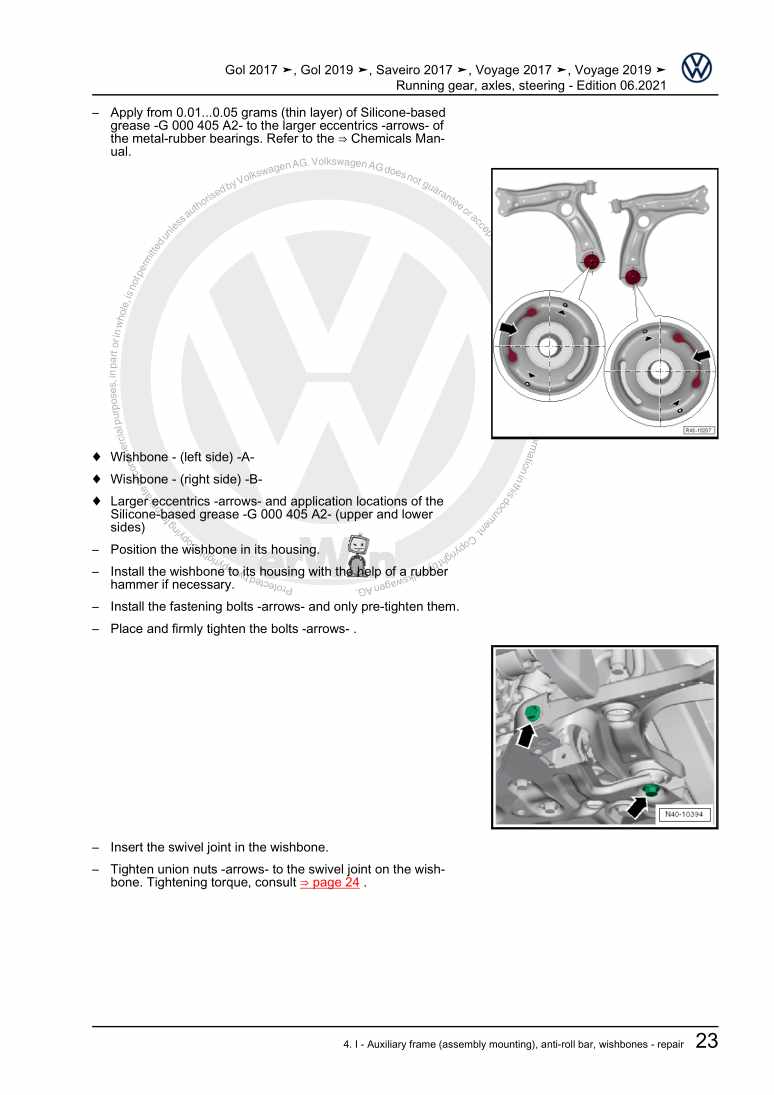
Running gear, axles, steering

Beispielseite für Reparaturanleitung Running gear, axles, steering

Für GOL BR (2017) / Voyage BR (2017) / Saveiro Cab. Dupla [BR] (2017 >) / Saveiro Cab. Sim. (2017 >) / Saveiro Cab. Est. (2017 >) / Voyage [BR] (2019 >) / Gol [BR] (2019 >)

23,15 € Details

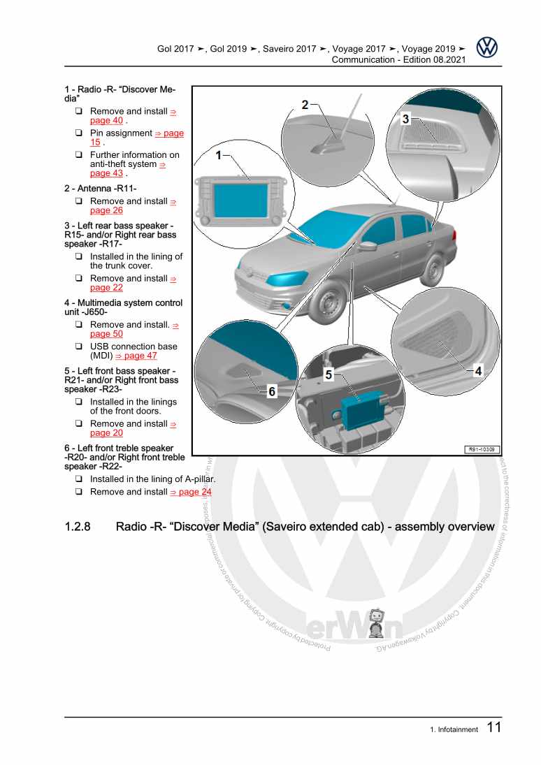
Communication

Beispielseite für Reparaturanleitung Communication

Für GOL BR (2017) / Voyage BR (2017) / Saveiro Cab. Dupla [BR] (2017 >) / Saveiro Cab. Sim. (2017 >) / Saveiro Cab. Est. (2017 >) / Voyage [BR] (2019 >) / Gol [BR] (2019 >)

7,19 € Details

Brake systems

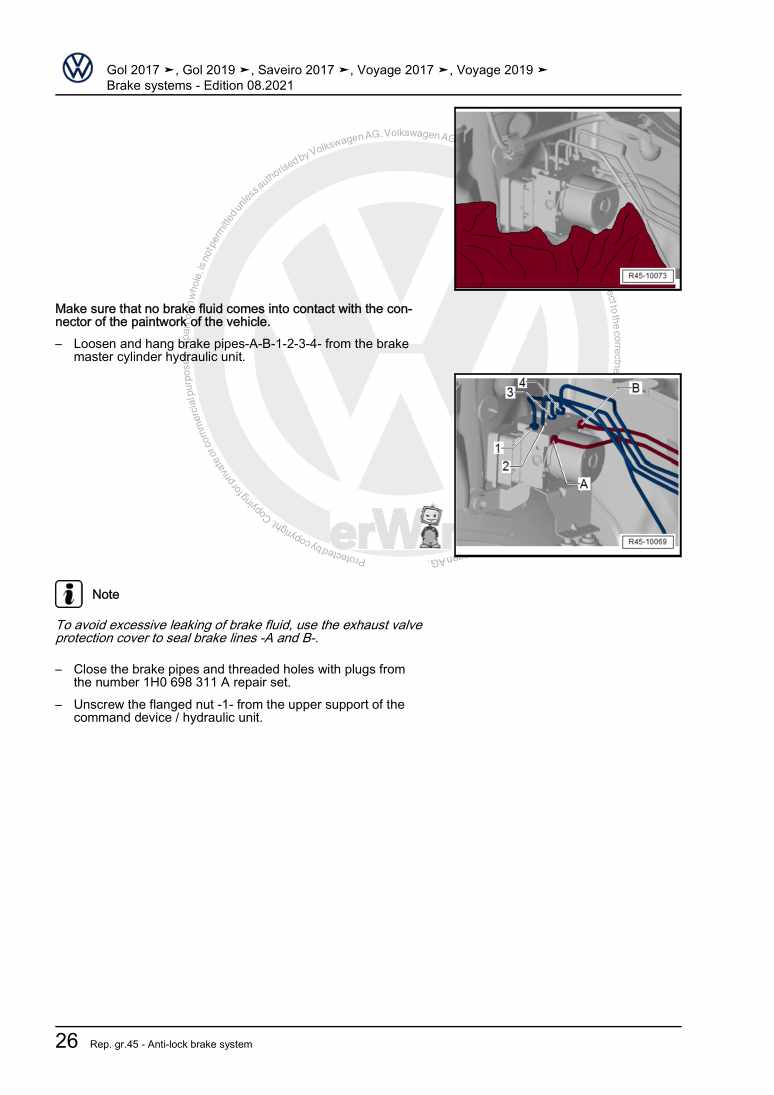
Beispielseite für Reparaturanleitung Brake systems

Für GOL BR (2017) / Voyage BR (2017) / Saveiro Cab. Dupla [BR] (2017 >) / Saveiro Cab. Sim. (2017 >) / Saveiro Cab. Est. (2017 >) / Voyage [BR] (2019 >) / Gol [BR] (2019 >)

13,49 € Details

Maintenance

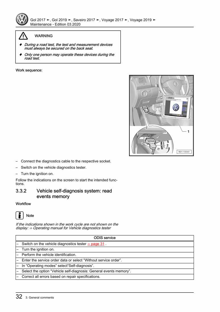
Beispielseite für Reparaturanleitung Maintenance

Für GOL BR (2017) / Voyage BR (2017) / Saveiro Cab. Dupla [BR] (2017 >) / Saveiro Cab. Sim. (2017 >) / Saveiro Cab. Est. (2017 >) / Voyage [BR] (2019 >) / Gol [BR] (2019 >)

10,19 € Details

General body repairs, exterior

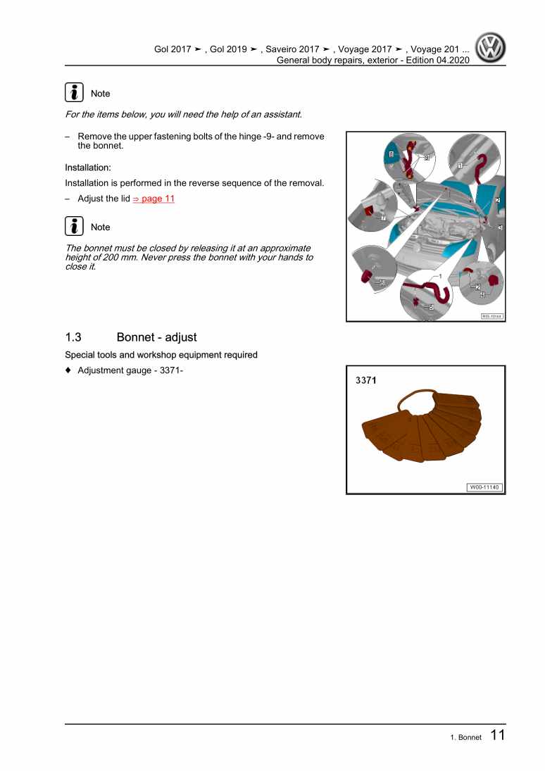
Beispielseite für Reparaturanleitung General body repairs, exterior

Für GOL BR (2017) / Voyage BR (2017) / Saveiro Cab. Dupla [BR] (2017 >) / Saveiro Cab. Sim. (2017 >) / Saveiro Cab. Est. (2017 >) / Voyage [BR] (2019 >) / Gol [BR] (2019 >)

27,65 € Details

Body Repairs

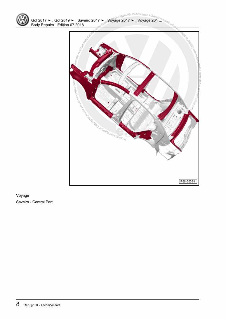
Beispielseite für Reparaturanleitung Body Repairs

Für GOL BR (2017) / Voyage BR (2017) / Saveiro Cab. Dupla [BR] (2017 >) / Saveiro Cab. Sim. (2017 >) / Saveiro Cab. Est. (2017 >) / Voyage [BR] (2019 >) / Gol [BR] (2019 >)

27,20 € Details

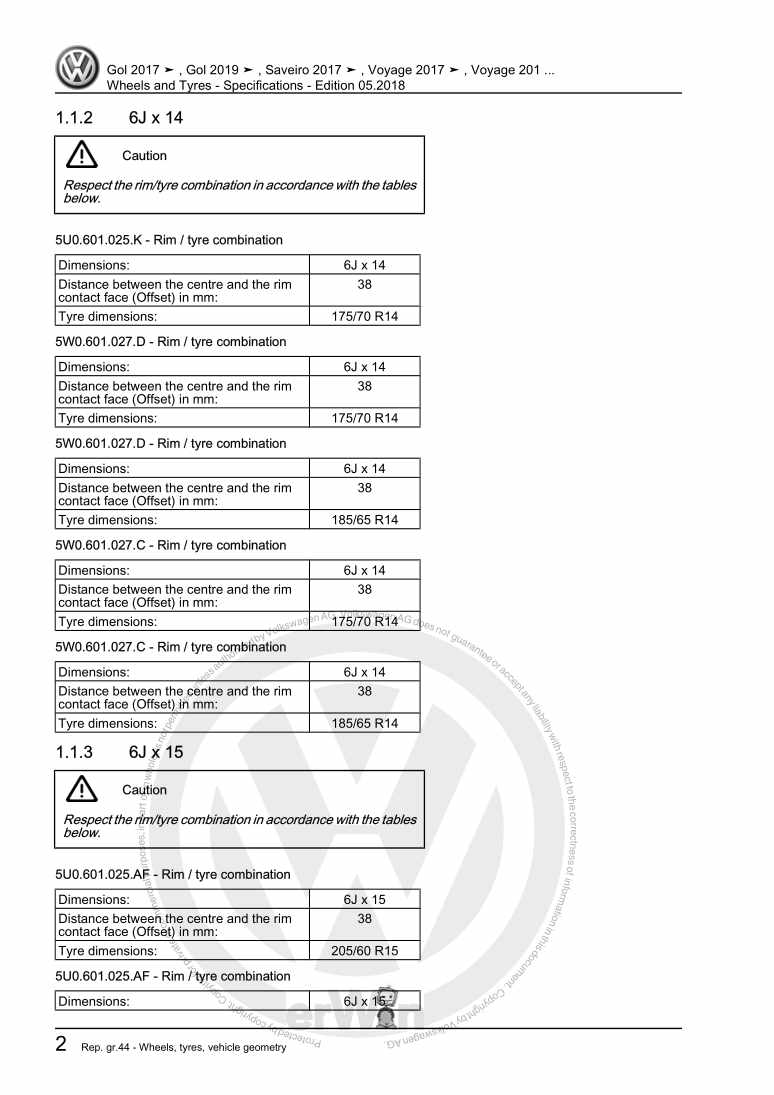
Wheels and Tyres - Specifications

Beispielseite für Reparaturanleitung Wheels and Tyres - Specifications

Für GOL BR (2017) / Voyage BR (2017) / Saveiro Cab. Dupla [BR] (2017 >) / Saveiro Cab. Sim. (2017 >) / Saveiro Cab. Est. (2017 >) / Voyage [BR] (2019 >) / Gol [BR] (2019 >)

4,27 € Details

Unsere Best Seller

Schon gewusst? Wir bieten auch originale Autoteile an.

Autoteil 2K588331882V Verkleid.

2K588331882V

Verkleid.

29,08 €

Details
Autoteil 4G8805607 Aufnahme

4G8805607

Aufnahme

34,69 €

Details
Autoteil 3Q0253574 Leitung

3Q0253574

Leitung

36,27 €

Details
Autoteil 5Q1815101D Wasserrohr

5Q1815101D

Wasserrohr

64,80 €

Details
Autoteil 8D0253115C Dichtung

8D0253115C

Dichtung

15,74 €

Details

7 Gang-Doppelkupplungsgetriebe 0GC Volkswagen R GmbH
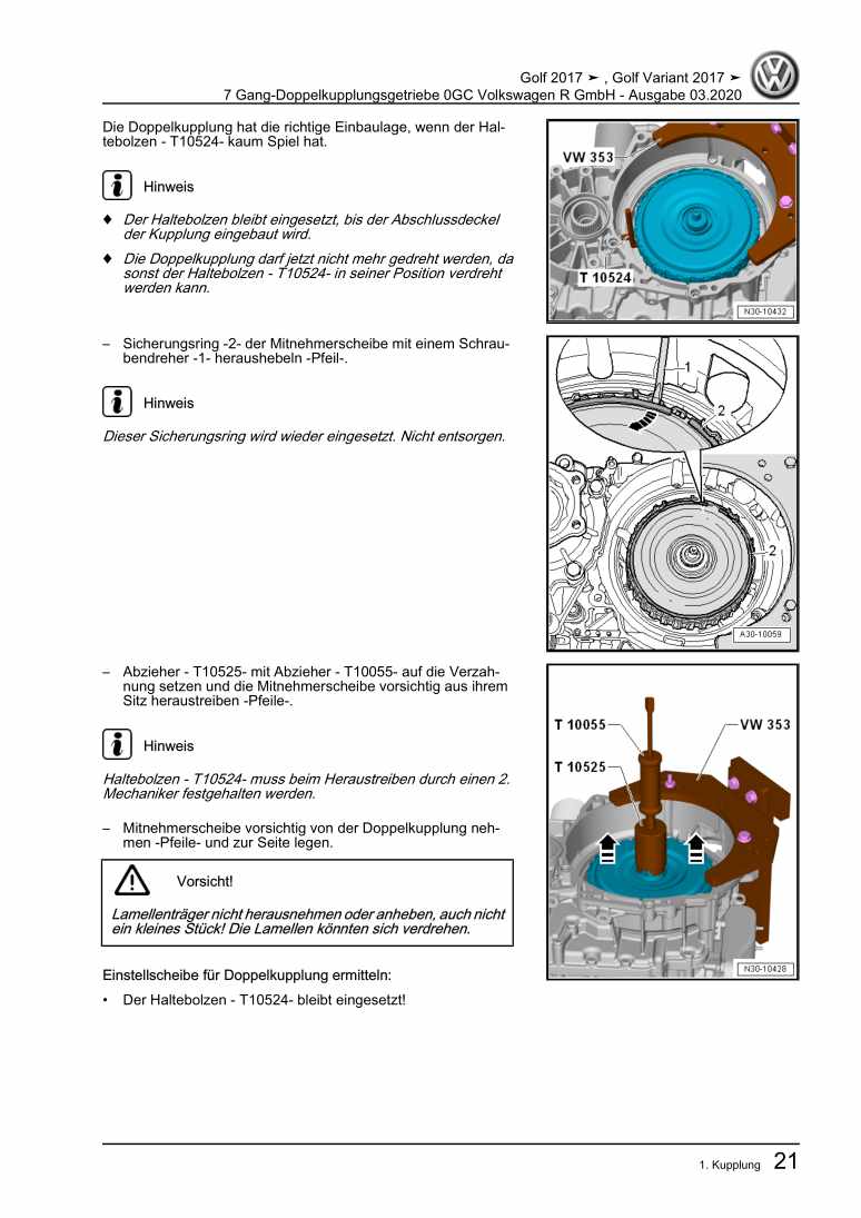
Beispielseite für Reparaturanleitung 7 Gang-Doppelkupplungsgetriebe 0GC Volkswagen R GmbH

Für Golf VII (2017) / Golf (2017)

10,54 € Details

4-Zylinder-Dieselmotor (1,9 l-Motor) 028.B / ADE / ADG

Beispielseite für Reparaturanleitung 4-Zylinder-Dieselmotor (1,9 l-Motor) 028.B / ADE / ADG

Für Industriemotoren - Industrial Engines ()

7,57 € Details

Eigendiagnose für Automatisches Getriebe 09A - 5 Gang
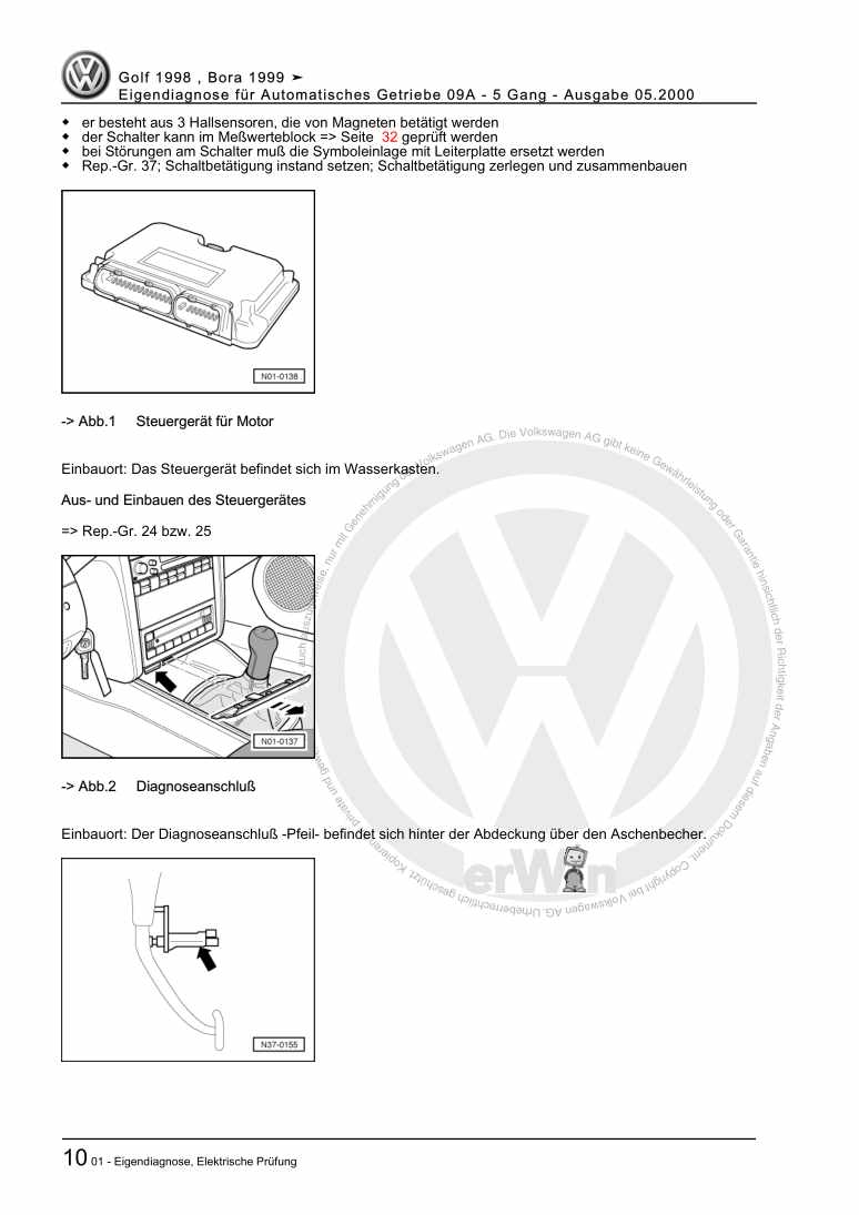
Beispielseite für Reparaturanleitung Eigendiagnose für Automatisches Getriebe 09A - 5 Gang

Für Bora / Bora Variant / Golf / Golf Variant (1998 - 2006)

6,00 € Details

image/svg+xml Über Clonck

Originale Reparaturanleitungen und Ersatzteile

Unsere Reparaturanleitungen sind Originale, kommen direkt von Volkswagen und erfüllen die höchsten Qualitätsstandards.

In unserem Originalteile-Shop verkaufen wir hochwertige Originalersatzteile der Fahrzeughersteller. Mithilfe der Suche gibst du die gewünschte Teilenummer (OE-Nummer) ein und bestellst schnell und einfach das benötigte Ersatzteil.

Höchste Qualitätsstandards

Bei Clonck wollen wir Autoschrauber und Kfz-Profis glücklich machen. Aus diesem Grund findest du bei Clonck ausschließlich professionelle und hochwertige Reparaturanleitungen, mit deren Hilfe du dein Fahrzeug fachgerecht reparieren kannst.

Unsere Partner

Autohaus Schmidt GmbH
Automag GmbH Filiale Laim
KFZ-VERLAG GmbH
Zimpel und Franke GmbH

Clonck: Der Autoreparatur-Shop - gibt's auch als App!

Clonck App Logo Play Store

Clonck: Passende Autoteile für deine Autoreparatur

4,5 90

Mit Clonck bestellst du die richtigen Originalersatzteile im Handumdrehen.
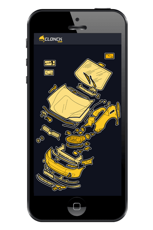
  • Fahrzeugmodell hinzufügen
  • Baugruppe auswählen
  • Fahrzeug-Identifizierungsnummer (FIN) eingeben
  • Über 5.000 originale Reparaturanleitungen einsehen
Jetzt App starten
Clonck App Preview Auto Mobiltelefon Autoteile